Introduction
The SocketBooster 1.0 exists to provide active conditioning for signals from our Ostrich2.0 and ChipExtender products. In some circumstances, the logic levels generated by these devices do not meet the specifications of the target device you are trying to use them in. The SocketBooster remedies this issue by essentially amplifying and conditioning the signal. In many cases, the same effect can be achieved by using a short emulation cable, such as the 6″ EMUC2806 we sell.
Ostrich 2.0 Trace Feature with SocketBooster 1.0
The SocketBooster 1.0 interferes with the data trace feature on the Ostrich 2.0 on an electrical level. However, one of our users reports that there is a fairly simple modification to get everything working again. We have not verified this ourselves, but several users have reported success with tracing on a 27C32 application and a SocketBooster.
"The mod to get it going is to cut the CS & OE ribbon cable wires from the
O2, and solder them to the 2732A header on the socket booster via a 330R
resistor."
SocketBooster 1.1 revision
We revised the SocketBooster around November 2013 so it could be compatible with the trace feature of the Ostrich 2.0. All units sold after this time should work without modification. If you would like to upgrade your unit, please contact us.
Applications
The socket booster is REQUIRED for successful use of the Ostrich 2.0 or Chip Extender with 24-pin applications such as the GM TBI OBD1 C3 1227747 ECUs.
The SocketBooster also seems to help out with a lot of applications that use older Hitachi/Mitsubishi processors such as DSM, 8 bit Nissan Z31/Z32/R32, etc. ECUs of this range are typically in the 84-91 year range.
Signs of Issues
The typical signs that your application may require a SocketBooster are intermittent ECM shutdowns, odd behavior, odd datalogging results, etc. Intermittent (or consistent) flaky behavior.
Installation and Use
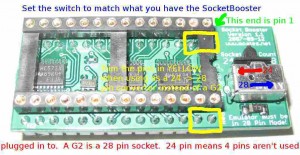
The Socket Booster has a single switch on it which controls how the device operates. The SocketBooster can either boost signals passing straight through it (28 pin setting) or act as a 24->28 pin converter (like the G2 we also sell) with the switch in the 24 pin position. Although we do NOT recommend this, you can solder a SocketBooster directly into a 24 pin ECM by trimming the two pins closest to the switch and setting the switch to the 24 pin setting.
