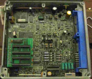
Versions
This is the documentation for the Nissan Boards. At this point, there are only one version of the boards, 1.1nm As future revisions to the board are produced, this page will be updated.
Applications
These boards are designed for S13 and B13 applications. They will NOT work with S14a ECUs that have a 20×2 pin header. They will not work with late S14/N14/etc. ECUs that have a 40×1 header. Known good applications:
S13 Silvia RWD “Red top” SR20DET (i.e. 62, E5, etc.) 240 swaps, etc.
S13 Silvia RWD “Black top” SR20DET NON VVTI (VVTI motors not supported) 240SX, etc.
S13 240SX KA24DE twin cam engine US Engine
B13 Sentra FWD SR20DE Sentra, etc.
U13 Bluebird SR20DET
About the Board Hardware
The 20×2 Nissan ROM board has two 28 pin sockets for an EPROM such as a 27SF512 or 27C256. These are not “even-odd” style boards – chips installed in this board should always have identical programs unless you REALLY know what you are doing. You will need to buy a ROM burner separately if you do not already have one – this board cannot program chips.
You can use two Ostriches with this board. Insert each Ostrich like it was an EPROM. Make sure JROM is not installed (see below for more) or you may have issues with addressing and Ostriches. You will need a 5.x version of TunerPro RT to have native dual Ostrich support. You can accomplish the same thing using TunerPro 4.x by also using EmUtility (available from tunerpro.net in the utilities section) to run one Ostrich in emulation mode while TunerPro natively runs the other Ostrich.
Switching and JROM
As previously mentioned, the 20×2 board allows the use of two programs with near instantaneous realtime switching. The JROM is used to change between two programs when using 512k chips (i.e. 27SF512 or 27C512). By default, the adapter uses a 32k program from 08000h to 0FFFFh. When JROM is present, the adapter uses the 32k program from 00000h to 07FFFh. You can mount an external switch for the jumper if you like. This link has more information about programming multiple programs and offsets.
Software support
This board has no copy protection that would prevent you using it with a particular software package. The technical answer to “software support” is to say that it will work with any software capable or providing a Nissan binary ROM file. Software I have tested these boards with:
- Tuner Pro RT ( www.tunerpro.net )
- 925style.com ROM Editor ( ask google “925style ROM editor” – original site is down)
- Nistune
Just to reiterate – any software that can output a binary file will probably work fine with these boards.
Installation
Installation of the Nissan 20×2 boards can be quite tricky. A proper de-soldering iron is required for good results.
- Remove both the top and bottom case from the ECU
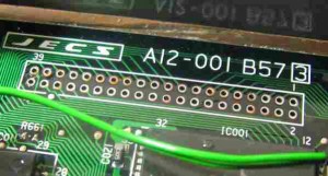
- De-solder all 40 pins of the 20×2 connector. remember, a clean de-soldering job is critical to this working correctly. Be careful not to overheat and burn any traces as this can be easy to do. When you are done, it should look something like this:
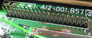
- Place the installed pin header in the 20×2 header so that the “notch” in the header faces towards the blue ECU connector:
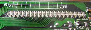
- Solder the 20×2 header in place carefully. Again, remember clean, accurate soldering is critical for this product to work correctly:
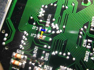
- Find the jumper marked “CJ1” – you will need to remove it and move it to position “CJ2” as this enables the use of the ROM board. (Putting the jumper back to CJ1 will enable the use of the stock program.) Be careful when doing this. The use of two soldering irons, a soldering iron and de-soldering iron or best yet – a set of SMD tweezers will make things much easier. If you damage the jumper removing it, do not worry – you can use a small piece of wire or a paperclip instead. (Trim any excess wire / paperclip if you use this method)
- Finally, slide the 20×2 board onto the installed header:
