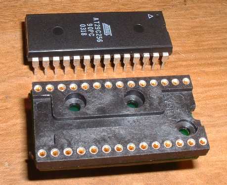
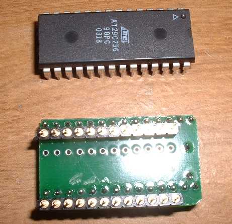
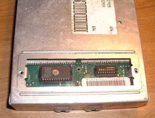
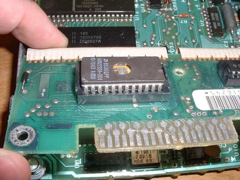
G2 TBI-Style 2732-to-29C256 Adapter Installation Instructions:Here is a pictorial depiction of a G2 installation in a TBI-style ECM.
It shows the following:
1) Disassembly and removal of stock socket body.
– Take note of the ‘stock’ 2732A chip orientation. Your 2732A chip will probably be in a little plastic holder.
– Try and overcome the challenge presented by the disparity between that fact and this pictorial guide.
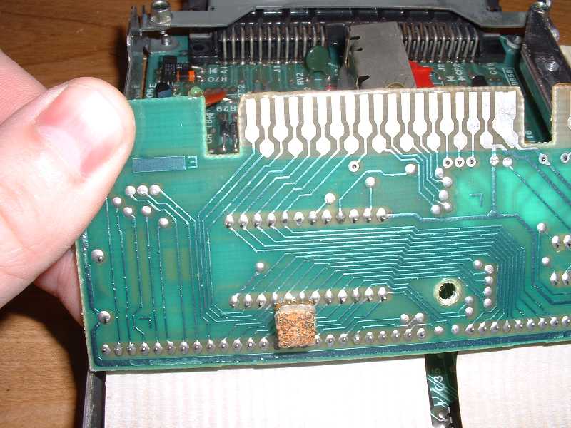
– Take apart the ECM case, loosen screws that hold ‘daughterboard’, and get everything free so you can get to the underside.
– Be careful with ribbon cables which are often glued to the ECM housing areas.
– Measure spacing between row of chip socket pins, and make sure you order the correct adapter part (0.6 or 0.45″).
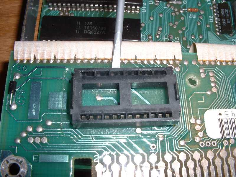
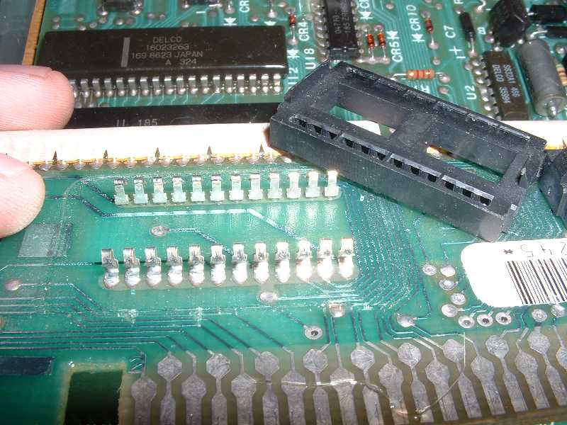
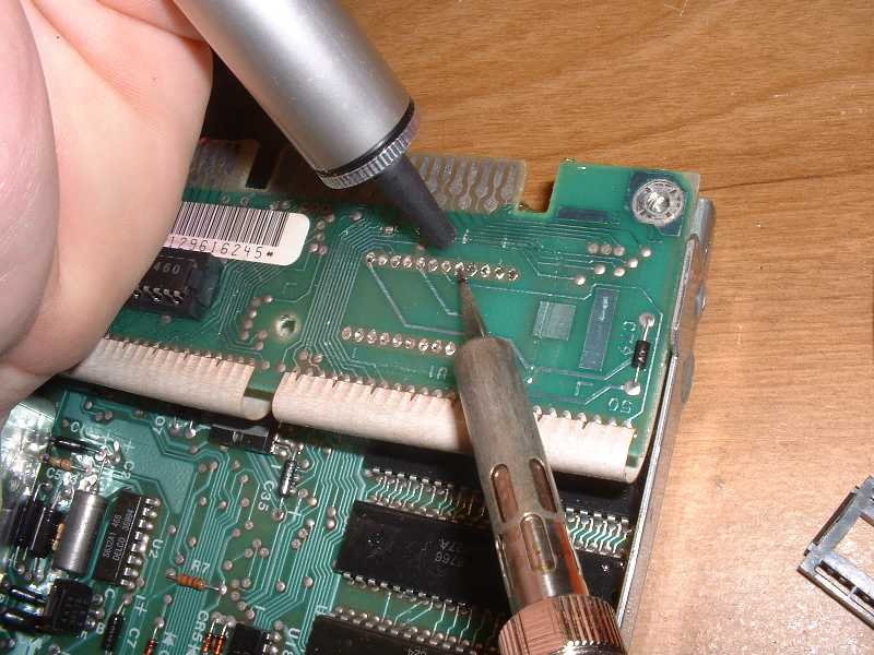
– Using small screwdriver, gently pry plastic off of pins. It should come free, leaving pins to be desoldered individually pretty easily. This may not work as well with 0.45″ spacing sockets, and you might have to desolder the whole socket at the same time or mutilate it a little bit to get it out.
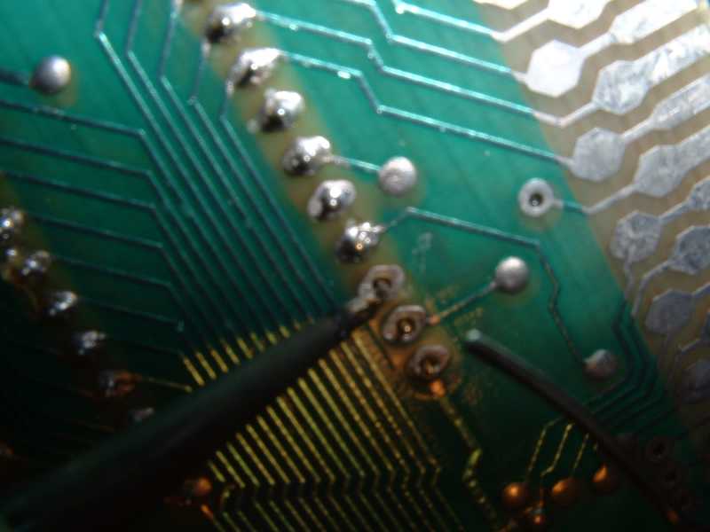
2) Desoldering of stock socket pins, removal of solder from holes using solder sucker.
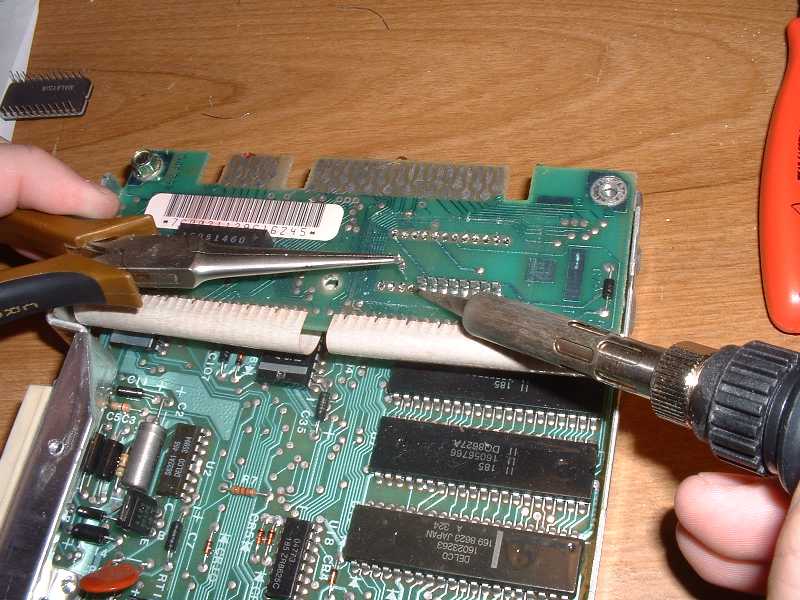
– Apply heat and remove each individual pin (assuming you were successful with step (1).
– Use solder sucker to open up each hole for acceptance of the ‘new’ socket.
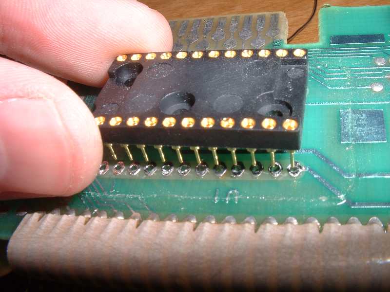
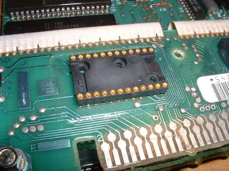
3) Soldering in place of a 24-pin collet-pin DIP socket. (For 0.45″ spacing, 12-pin SIPs are used instead).
– Just like it says. If you want a very low profile install, skip this step and go to step (4), except solder it in place instead of pressing it in.
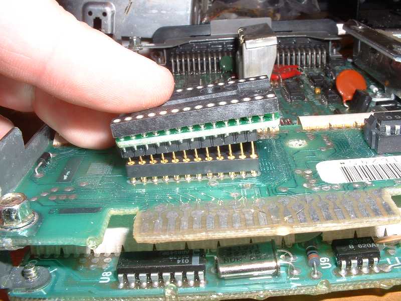
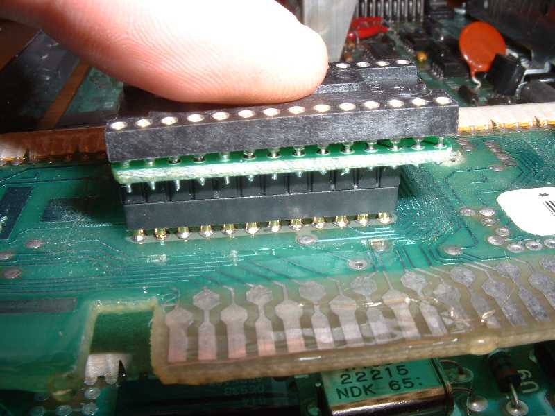
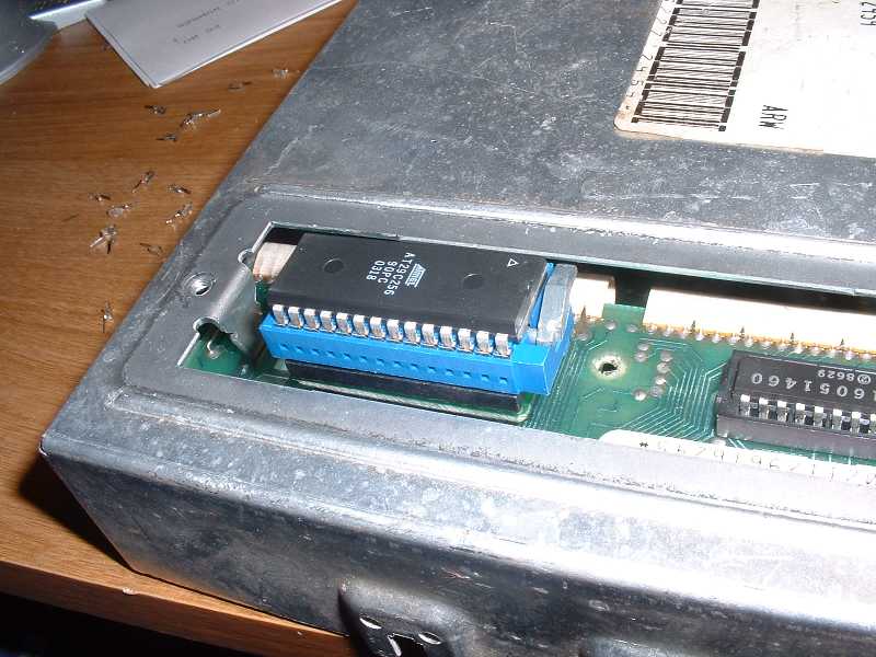
4) Placement of G2 adapter along with optional ZIF and associated chip.
– Just like it says.
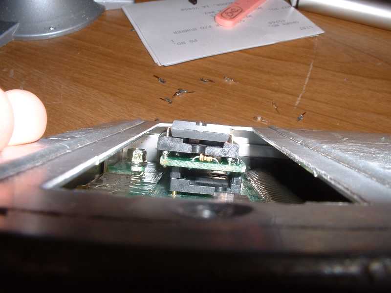
5) View of relative clearance and reassembly.
– Check and make sure it’s not going to hit anything when installed back in the car. If you have clearance issues, you might want to consider the solder-in option mentioned in (3-4).
Note that the height can be reduced by not using the ZIF socket, and can be further reduced by soldering the adapter directly in as mentioned (bypassing the DIP or SIP socket install).
These pictures should give you the information you need with respect to procedures, relative socket / adapter / chip orientation, etc.
However, if after viewing this you still have questions, just let me know at my email address on the main page and I’ll do my best to field them.
Have fun!


|


