Ground loops, or why power inverters can fry things

Quick Explanation / TL;DR: / READ ME

If you have called to ask for help, one of the things we often ask you is, “Are you using a power inverter to power your laptop?  Do you have your laptop plugged in to the wall?”

There is a reason for this, and we see product get killed every year because of it.  If you don’t want the “why” and just want to know what to do, stop reading after this next line (or skip to the more detailed “solutions” section at the end):


DO NOT PLUG POWER INTO YOUR LAPTOP WHILE YOUR MOATES DEVICE IS CONNECTED TO ANYTHING ELSE, LIKE YOUR CAR!!!


Full Explanation Why

Alternating Current (or “AC”) does not rely on ground to operate, guaranteeing only the difference between two terminals and that the voltage periodically changes polarity (plus and minus “alternating”).  AC is what comes out of the wall in most electric grid delivery.  Direct Current (“DC”) is what comes out of batteries and other DC power sources.  With DC, potential stays one direction without changing polarity and voltage produced by a battery is expressed as a positive number of volts.  The negative terminal of the power source is generally assumed to be where you are measuring from when talking about DC.

Ground is not zero volts.  Ground, electrically speaking, is just the place we agree to call zero.  It’s just a convention, a spot to measure from.

AC can have both a negative and positive component with respect to ground.  It can also be entirely positive with respect to ground.  It can also be entirely negative with respect to ground.  As long as the DIFFERENCE between the two AC terminals varies according to specification, they can be valid AC.  For instance, two wires varying between -220 and -100 volts and two wires varying between 50 and 170 volts can both be 120VAC because ((-100) – (-220)) = 120 and ((170) – (50) = 120.  It doesn’t matter that neither of these AC voltages is centered around what we are calling zero volts (“ground”).  In most residential electricity, the “neutral” wire is supposed to be connected to earth ground (literally, a stake in the ground) at the power distribution box but this is not required for AC current to be present – only the varying voltage potential between two points is required even though neutral really is earth ground in most residential electric.

DC is generally (but not always) expressed as a positive voltage with respect to ground.  If you were to reverse your multimeter’s leads and connect the minus lead to the positive terminal of the battery, the chassis (assuming the negative terminal is connected to the chassis) would measure -12V.  The voltage supplied by an ECU to a throttle position sensor is generally 5V, with respect to sensor ground.  If you were to measure the voltage at the TPS sensor +5v supply with your multimeter ground connected to the +12v terminal of the battery, you could expect to see (+5V –  +12V) = -7V instead of +5V.   If you move your multimeter minus terminal to the TPS- pin, you should see +5V between TPS- and TPS+ reference.  The voltage didn’t change – how you observed it changed because of where you chose to call ground.

Ground is just a convention that we agree on.  If you do funny things with ground, you will get strange results.

If you have AC voltage without an explicit ground, you have an infinite number of ways to make DC from it.  In most cases, AC-DC supplies pick a potential in the middle of the AC range and “call it” ground.  They then use electronic components to create a voltage that is always a fixed difference from the AC voltage picked and call this the output.  The AC-DC supply provides BOTH “ground” and “supply” as outputs.  As long as whatever DC load is connected only ever sees these ground and supply terminals, it will operate perfectly as it has a constant voltage potential (DC Voltage).  For most common DC devices (cellphones, laptops, etc.) this is perfectly acceptable because the electrical energy inside the device is largely self contained and it doesn’t need to interface with other devices powered by DC.  For sake of an example, let’s assume that we stick our multimeter minus lead into the ground.  Our AC input measures -60V to +60v with respect to the earth, for 120V total difference.  Our power supply outputs +42V and +30V with respect to the earth.  The difference between the output terminals (+42V, +30V) is +12V, and a 12V DC load would be perfectly happy.

If you have a DC voltage and you want to create a AC voltage, there are also an essentially infinite number of possible ways to do it.  As long as the difference between the outputs measures appropriately and the signal switches like it should, an AC device should function correctly.  If we agree that ground is the negative battery terminal, our power inverter plugged into a cigarette lighter socket on a vehicle receives +12V and 0V from the battery.  It can output a voltage that swings between +120V and 0V.  It can output a voltage that swings between 0V and -120V.  Both of these will be A-OK for something plugged into the power inverter looking for AC because the difference between the AC outputs varies by 120VAC.

So what happens when we take our example AC-DC power supply (supply +60/-60: receive +12V in the form of +42V and +30V) into our power inverter supplying +0V and -120V?  The power inverter is giving a 120V AC output so the AC-DC supply works fine.  The AC-DC supply chooses 18V below max input (+60V – +42V) for its output and 30V below max input (+60V – +30V) for its output.  The AC-DC supply is being fed 0V maximum and -120V minimum.  It outputs 18V below max input (-18V) for its output and 30V below max input (-30V) for its “ground” coming out, which is a difference of +12V (-18V – -30V) so completely acceptable to run our 12V widget that we’ve plugged into the inverter.

But what happens if our widget, powered off -18V and -30V, gets connected by a USB cable to the vehicle?  If we measure all of our supply voltages from the same spot, -30V is a different potential than the terminal of the battery, which we agreed was “0” when we called it ground.  This difference in ground voltage supplied to two devices with a connection in between is called a “ground loop.”  Ground loops happen when two wires that are both supposed to be at the same ground potential get connected together with power supplies driving ground to different absolute voltage potentials.  If you have two power supplies that are trying to push “ground” to two different voltages and you connect them together but they don’t agree about where “zero” is, so you end up with current flowing from “ground” of one power supply to “ground” of the other power supply, trying to equal things out.  Most of the time, the small cables (USB, ribbon, etc.) supplied with our devices which provide the path from one ground potential to the other aren’t cut out for supplying many amps of power than can be supplied by a modern DC power adapter, leading to far more current flowing through wires that were not designed for it.  Heat, smoke and damage are the usual result.

When a laptop is running off battery, the battery provides voltage from chemical energy stored in the battery and the positive voltage output will always be relative to the battery’s negative terminal, regardless of the absolute potential of the negative terminal.  A 12V battery will measure +112V at the positive terminal when the negative terminal is connected to +100V because the chemical energy will create a DIFFERENCE (112V -100V = 12V) in voltage.  This allows the ground terminal to “float” to whatever voltage is convenient, usually determined by whatever the laptop is connected to.  Having a USB cable connected to a device connected to the chassis ground of the car doesn’t result in a lot of current flowing from the laptop’s negative battery terminal to the car’s negative battery terminal because the battery can work with the negative terminal floating, so it isn’t trying to drive ground to a difference absolute potential, only power the laptop with a relative difference in potential.  However, when running off an AC adapter, the AC adapter has to drive ground to a specific potential in order to be able to supply the positive voltage it needs to charge.  This is where the opportunity for things to go wrong starts.
There needs to be two power supplies with two different grounds for chaos to ensue.  This generally means that there is also a AC-DC conversion happening where ground gets “lost” somewhere along the way.  Some examples of two power supplies where things can go wrong:
  • Car battery (12V and ground), DC-AC inverter plugged in to the cigarette lighter(120V AC out with no common ground reference), AC-DC power adapter plugged in to inverter (+18V and “ground”, with ground floating somewhere between the voltages coming out of the inverter) connected to a Laptop with its USB ports connected to AC-DC adapter ground.  Ground loop forms from AC-DC power adapter “ground” through laptop through USB port through USB cable to device connected to car battery ground.
  • Bench power supply (providing 12V and ground) to ECU connected to laptop powered by AC-DC adapter (providing +20V and ground).  Laptop and ECU connected by USB port ground, AC adapter for laptop and AC-DC power supply for ECU trying to achieve different “ground”
  • Car battery (12V and ground) connected to DC laptop charger.  DC laptop charger creates 20V to charge laptop but does so with a “hidden” DC-AC conversion coupled with an AC-DC conversion.  DC goes in, DC goes out but ground is “lost” in a hidden AC conversion in the middle.  By the time DC comes out, ground potential has shifted from ground supplied to it.  Ground loop forms from laptop ground connected to floating ground of DC-DC converter and battery ground of car connected to ECU connected together by USB ground wire.

So why don’t you just isolate all your Moates devices?

If we used isolated communications on all of our devices, you would need to power all of our devices independently of your laptop in order to communicate.  This would mean all our emulators would need the key on to be able to load a program to them.  This would mean you’d need the vehicle powered to retrieve logs from any device that had onboard logging.  When devices were designed, it was decided that the convenience and utility of having the laptop power up the device enough to communicate with it outweighed the dangers and disadvantages of potential ground loops.  For both the laptop and ECU to be able to power a Moates device, there needed to be a shared/common ground.  With a shared/common ground, the possibility of ground loops exists.  For better or worse, this is how things were designed and they’re not changing now.  When connecting to any Moates USB product, you need to be aware of ground loops and the havoc they can cause.

Solutions for ground loops?

What can you do about this?
  • The standard recommendation is “don’t run your laptop on a charger/inverter.”  This allows ground of the laptop (which is connected to pins on the USB port) to float to whatever potential it is connected to instead of being driven to a certain potential by a charging adapter.
  • Another solution is to explicitly tie the laptop’s ground to the power ground supplied to the ECU and link the chargers together, but be aware that whatever wire you use to do this may need to carry a significant amount of current.
  • Using chargers which explicitly reference a common ground potential and don’t try to push ground to two different places would be ideal, but it’s often hard to determine how power supplies are designed prior to purchase.
  • If you have to use two different power supplies (car battery and inverter+AC adapter, two AC adapters, etc.) use a multimeter to measure the voltage between the ground pins with them plugged in and powered.  If it isn’t zero volts, you’re almost guaranteed to have a ground loop.  You can also unplug everything so no adapter is powered and measure the resistance from one ground to another.  It should be low, ideally zero.  Anything more than a single digit number of ohms is likely to give you a ground loop.
  • Using isolated communications is another solution.  These may not be available for all devices but most of our emulators and “active” gear have a 4 pin port for direct communication, which would allow either the BT or Iso options, with an appropriate cable.  (Pinouts are documented.)  The two things we sell to enable this are:
    • Bluetooth interfaces (there are no wires – communications happens over radio energy)
    • The Optoisolator cable. (which uses a device that turns electricity into light to allow communication without an electrical connection)

Turbo Mopar 85-93

We don’t have a lot of experience with these vehicles but they have a decent community providing tools for tuning the factory ECMs.  Many of the ECMs can directly use 28 pin EPROMs like the SST27SF512 and BURN2 we sell and an Ostrich 2.0 for live tuning.  Other ECMs use 87C257 chips which require a “latch board” to use standard 28 pin chips like a SST27SF512 or 27C256 (or an Ostrich).  These latch boards are available from Meyer Tuned.  The Turbo Mopar EFI Tuning Forum is a good place to start for more information on tuning these vehicles.

About the “Data Trace” feature of our chip emulators

Introduction

The ‘Data trace’ feature of our emulators is probably one of the most misunderstood features.  Trace is intended to give you some idea of what portions of an emulated ROM are being used by the target system as a last resort when you don’t have a way of establishing communications for logging.  Trace is a feature supported only by the Ostrich 2.0 and RoadRunner (with latest firmware).  This article exists to document what Trace is, how it works, what it can do, what kind of limitations exist and how it can go wrong.

In order to understand how data trace works, it is necessary to understand the electrical signals used by a microcontroller in your ECU (or target system) to access RAM or ROM using parallel access.  There are many explanations of this out there but this one seemed decently concise.  It will also be necessary to understand the commands used to set up Trace and the mechanism that the emulator uses to gather and report data back to the PC, along with what happens to that data in the application running on the PC.  It will also be very helpful to understand TunerPro RT definition creation.

Bottom line: Trace is complicated, finicky, temperamental and is not designed to provide the same kind of steady, consistent data that can be obtained through communicating with the ECM using some form of data logging.  Our emulators were NOT designed from the ground up to provide 100% accurate address trace data and we do not expect them to be able to deliver that level of performance.

What Trace is and How it Works

Normal operation of the emulator is the PC sending commands to the Emulator to make changes to emulator memory, allowing changes in a “chip” to be made without having to stop, remove, reprogram and reinstall the chip.  The Emulator has a microcontroller which is responsible for receiving and processing commands from the PC and communicating with a memory controller.  In order to allow changes to be made without disturbing the target system, our emulators sneak updates from the PC in between accesses by the target system.  (If the target expects data too fast, glitches may occur caused by collisions between PC and target memory access.)

Trace allows an application that sends the specific appropriate setup commands to the emulator to monitor which addresses the target system accesses.  When trace is enabled, the microcontroller on the emulator starts querying the same memory controller used for realtime updates to see which addresses are queried by the target system.  In order to determine which memory is accessed, two main signals are monitored by the memory controller:

  1. The address lines on the emulator, used by the target system to specify which data it wants to see
  2. The !OE (Output Enable) and !CE(chip enable) pins, which are used by the target to control the timing of a data output request

After the control lines indicate memory access, the memory controller stores the last address used by the target system.  As fast as it can, the microcontroller retrieves the address information from the memory controller.  Addresses responses are always 3 bytes and take (minimum) 8 MCU clock cycles or around 0.6uS to retrieve from the memory controller.  Setup commands sent by the PC control how the Emulator handles each address retrieved from the memory controller.  It can either store/buffer, send to PC or ignore the received address and wait for another hit.  If you are curious, you can look at the setup command structure in our documentation.  It is possible to control the range of addresses which trigger a match, the number of address hits to gather before reporting to the PC, whether addresses are streamed continuously or reported once before returning to normal control, whether duplicate hits are reported multiple times or once, the format of responses in terms of number of bytes reported and more.

Our emulators communicate with the PC at 921,600 baud 8N1 over a FTDI USB-Serial connection.  This means that approximately 102,400 bytes can be transferred each second, and each byte takes about 10uS to send.  The system is bandwidth-limited because it can gather trace responses from the memory controller faster than it can supply them to the PC.

Software Support

At this point (April 2020) the only softwares that have implemented support for data trace that we know of are TunerPro RT and RenoVelo Domino.  Specific software support for the trace feature is REQUIRED.  An application that supports the realtime tuning / emulation features of our products (i.e. EmUtility) may NOT support trace at all.

While we do not develop it in house, TunerPro RT is our reference platform that we use internally for testing and product development.  There are two methods of using the Trace feature of a compatible emulator in TunerPro RT.

The Address Watch Utility: (Note: it is “greyed out” / unavailable in this screenshot because I didn’t have a compatible emulator plugged in)

TPRT - Address watch utillity


Trace can also be invoked to watch individual tables: (again, “greyed out” / unavailable in this screenshot because I didn’t have a compatible emulator plugged in)

TPRT - A for Address

Looking at the control protocols, an example auto-generated “T” command sent by TunerPro RT to the emulator to set up trace after clicking the ‘A’ icon appears to be

"54 23 00 00 01 01 08 44 38 08 44 73 BC    /      T#.....D8.Ds."
  • Control byte = 23: 0b00100011
  • NO streaming
  • report only windowed hits
  • report all
  • normal addr triggers
  • relative addressing
  • single hit buffers
  • single byte address report
  • windowed report (relative  vs. absolute address reports)


What can go wrong with Trace? / Limitations

I’m sure Trace sounds great, like the perfect solution for ECUs where limited communication is possible.  Unfortunately, there are many ways for trace to go wrong and not act like you might hope or expect it would.

  1. Memory controller limitations: missed hits inside the emulator.  The memory controller does not buffer memory hits.  It only reports the last accessed address.  The speed at which the microcontroller queries the memory controller limits how many hits can be captured.  As discussed, it takes several MCU clock ticks do retrieve data from the memory controller. In ~0.6uS, at least 5x 100nS memory accesses can happen, all of which would be missed by the trace system.
  2. Processing received addresses: missed hits inside the emulator.  It takes time (albeit a VERY short amount of time) for the microcontroller on the emulator to process address hits and decide what to do with them.  As it does not query the memory controller when deciding what to do with an address hit, this limits the speed at which it can query the memory controller and limits how many hits can be captured.
  3. Bandwidth / PC: missed hits due to serial comms.  This bandwidth and latency limitation is inherent to the hardware design and will not change.  There is very limited bandwidth to communicate with a PC compared to the speed of memory access.  It takes around 10uSec to communincate the shortest format abbreviated address hit in streaming mode.  That means around 100 memory accesses (at 100ns) can occur (and be missed) by the target during the time it takes ONE Trace hit to be communicated with the PC.  Multiple byte responses (which will be necessary for larger monitor windows) will require 2 or 3 times as long for communication.  These are best-case figures, assuming streaming mode.  If a single response is sent followed by a new command setup, the latency of the process could be increased by a factor of 20 easily.  (Note: single response is the default monitoring scheme for TunerPro RT commands.)  If a large number of address hits are buffered and then bulk transferred, the latency between each hit is significantly decreased but the time to communicate with the PC is significantly increased, leading to a longer pause in between each group of responses.  Bottom line: serial communication limits the maximum potential address hit capability to a fraction of bus speed.
  4. Addressing mix-ups: software/XDF.   Under XDF … Edit XDF info it is possible to specify chip size, offset parameters.  TunerPro uses the address of the table in the XDF for the start and stop addresses it sends as part of the Trace setup command.  The XDF setup parameters control the relative location of tables within TunerPro’s memory model.  These need to be specified in a way that the addresses TunerPro RT uses for representing the bin on your PC match how the Ostrich stores the bin in its memory.  The addresses matching allows TunerPro RT to match the Trace command responses it receives from the emulator with the correct bytes stored in PC memory and show you which bytes in a table are being accessed.  If the memory models differ, TunerPro RT will never show any bytes in the table being accessed because the responses to the Trace commands don’t match with the information it has in memory.
  5. Memory Shadowing: target system behavior: “Shadowing” refers to the practice of an embedded system copying memory from one place to another before using it.  In many cases, slow flash or ROM chip memory is copied to faster RAM memory and then accessed in RAM during normal operation.  In this style of use, there are no ROM accesses to trigger Trace hits after the initial shadow.  While this does not often happen, it is controlled by the target system and is not under the control of our emulators.

Conclusion

Trace was a “nifty extra” added to our emulators because we could and figured it might be handy in some cases.  We did NOT design our emulators around being able to deliver completely accurate and precise address tracing.  We do not have any plans to improve the data Trace feature.  We do not have any plans to release an emulator that has better trace performance.  Our emulators were designed to take the place of a chip and allow realtime changes – this they do well.  Trace should be considered a “bonus feature.”  Do not rely on it to gather all the data needed to tune an ECU.

88-89 Fox Body V8 MAF oddballs: A9S / 8LD

Introduction

The Fox Body Mustang switched to using a Mass Air Flow meter to measure airflow in 1988 in California.  Box codes “A9S” and “8LD” are known examples.  Uses TFI distributor, sequential injection for up to 8 injectors, MAF air metering.  This particular EEC-IV system became the blueprint for the popular A9L / GUFB used by the rest of the Fox body platform.  These early oddball ECMs are very similar to their A9L / A9P / etc. cousins but are just different enough that they require their own unique bin files and definitions.  It is trivially possible to swap a later A9L/A9P/etc. ECM into a car using a A9S/8LD or vise versa.

These ECMs are known to have the hardware ID “SFI-MA2” and it is unknown which other hardware IDs can run the GUFA strategy.

8LD labelonly

Hardware for Tuning

  • QuarterHorse – integrated device brings unique functionality to the table.  It is a “chip on steroids” that allows you to make changes while the vehicle is running and (with supporting software) log live data from the vehicle.
  • F3 – simple chip module that can store one or two tunes and switch between them while vehicle is running.  Requires Jaybird programmer or BURN2+FA.
  • BURN2 + FA + FE – generic chip programmer with Ford adapter (FA) and ECM interface (FE) that can be used to read the current program from EECIV and EECV ECMs on the bench.

Software for Tuning

Although similar to their cousins, these ECMs can only run the GUFA code which uses 32k binaries instead of 56k.  At this point, Binary Editor is the primary software which supports these ECMs.

  • Binary Editor ($100 – $171 available from Moates.net) is a Ford-specific graphically oriented tuning software that supports many EEC-IV and EEC-V processors.  There are several options for BE:
    • Free built-in definitions for BE2012 come with the software.  They’re reasonably complete and work really well.  Support GUFB (A9L, etc.) GUF1 (A9P, etc.) and GUFA (others) natively
    • Core Tuning definition (available through Coretuning.Net) – uses same standards for organization as other Core Tuning defs, very complete.
    • EEC Analyzer ($50 available from Moates.net) is an optional companion program to Binary Editor to assist with analyzing data and automating tuning tasks.

Recommended Combos

Just want to know what to buy?  All of these will be valid combos that will allow you to tune a vehicle effectively.

(Ford Dealer Kit)

(QuarterHorse AND Jaybird AND F3 AND Binary Editor WITH Dongle AND wideband)

(Jaybird AND F3 AND Binary Editor )

Ford – Speed Density ECMs

Introduction

The first EFI ECMs used by Ford were speed-density featuring a MAP sensor and either a manual or hydraulically shifted automatic (C4/C6/AOD/etc) transmission along with electronically controlled ignition advance with a distributor.  They’re commonly found on early fuel injected Ford trucks like F150, 250, 350, Broncos and even early speed-density 5L mustangs/crown vics/etc.

Later models added AOD-E and E4OD electronically shifted transmissions.

The first generation Lightning trucks came with a speed-density 351 and a E4OD transmission.

These ECMs batch-fire injectors.  Swapping to later ECMs typically provides a slight improvement in fuel economy when the replacement ECM uses sequential injection.

As a rule of thumb, software support is very limited for these models compared to MAF vehicles like Fox Body A9L platform.  These may not be the best choice for a beginner or someone without prior tuning experience.  Be warned.

Strategy/BIN Swapping

While support in general is very limited for these models, there are a select few models/applications that are well-supported.  Fortunately, it is sometime possible to “swap strategies” and use a bin file that has software support in an ECM which otherwise lacks direct support.  Unlike MAF ECMs, the specific combinations of engine components factor highly in each particular speed-density calibration.  Use of a well-supported bin/strategy with a different engine than it was originally intended will often require major tuning due to differences in cylinder count, engine displacement, compression, camshaft.

The easiest way you can figure out which strategies will interchange is to match the hardware ID on the label of the ECM.

C3P1 EFI-SD48B

C3P1 EFI-SD48B HW ID

This is an “EFI-SD48B” ECM.  Any bin/strategy that runs on it (including a first generation lightning C3P1 / LHBL0 / LHBL1 ) will also run on other EFI-SD48B ECMs, and probably EFI-SD48E etc.  I don’t have an exact guide for swapping but if it is very close it’s at least worth a shot.

This document will be published incomplete and added to as I find more information and details.

Supported Hardware-Software Combos

These are known working combinations.  Each of these corresponds with a specific hardware ID or IDs known to interchange.

EFI-SD4x family: speed density, E4OD transmission.  Native to Bronco, Lightning, F150, F250, F350 approximately 1992-1995

  • Box codes C3P1, C3P2, C3p3 (1st gen Lighning), ICY1, T2X1, many more
  • Hardware IDs EFI-SD48B EFI-SD48E and more
  • LHBL0 / LHBL1 strategies will run on the hardware, maybe more
  • Supported by Core Tuning definitions ( www.coretuning.net ) LHBL1 strategy
  • Supported by Binary Editor (maybe?) via LHBL1.xlsx definition (BE website)
  • Supported by Decipha’s speed-density definitions for TunerPro RT ( EFI-SD4X [A1C] www.efidynotuning.com )
  • Decipha suggests that his definitions for TunerPro RT will work for “EFI-SD4x” implying that broad strategy/bin swapping is possible.


EFI-SD2X family: speed density, C4/C6/AOD non-electronic transmission.  Native to F150, Bronco approximately 1985-1993

  • Box codes 8PZ and more
  • Hardware IDs EF-SD20B and more
  • Supported by Decipha’s speed-densite definitions for TunerPro RT ( EFI-SD2X [C9C1]  www.efidynotuning.com )


SFI-SD1 family: 87-88 Mustang 5.0 speed density


Z2D1 / EFI-SD47B / F2TF-12A650-AHB: Supported by EEC Editor def/dlm edit/log via Z2D1 specific.  May also work with other options.


Unsupported/Unknown Hardware-Software Combos

SFI-SD3 / EA2 1988 Lincoln town car


85 Corvette TPI 1226870

Introduction

Unfortunately, the 1226870 is an oddball one-year one-model ECM that was only used on the 1985 corvette.  It is for a TPI setup with an electronically controlled distributor and features 160 baud ALDL communication for logging.  It is a unique ECM.  There are no other ECMs that are a “plug and play” swap without extensive wiring changes. (see “ECM Conversions” below) The ECM uses a 24 pin 2732 EPROM.  A G2 0.6″ chip adapter (solder/desolder install) can be used to install a 28 pin chip or use any of our OBD1 GM tuning gear.

No other masks from other ECMs can be trivially used.  It uses the $1F mask, which is supported by TunerPro RT.

Hardware Required for Tuning

  • G2 Chip adapter and C2 27SF512 chip required to reprogram ECM.  WARNING: This is NOT plug and play!  Desoldering factory chip is required and soldering install for G2 adapter.  (view install)  Order the “Install Service” and send us your ECM if you’re not comfortable with soldering work.
  • BURN2 Chip Programmer programs 27SF512 chips
  • ALDU1 with CABL1 required for datalogging
  • Ostrich2 and SocketBooster 1.0 required for real time tuning
  • APU1 AutoPROM All-in-one device works great (without SocketBooster), taking the place of BURN2, ALDU1+CABL1 and Ostrich2
  • APU1 works great for the application and is the recommended hardware in addition to the G2.

Software Required for Tuning

These computers use the $1F mask from the factory.

TunerPro RT + the $1F definitions works for editing and datalogging.  (this is the recommended software.  It is included with the AutoProm)  Additional/alternate definitions available from Gearhead-efi.com

TunerCat OBD1 tuner with the $1F definition works for editing.

WinALDL works for datalogging.

ECM Conversions

(disclaimer: blatant opinion) The 1226870 is not the high point of OBD1 GM engine management.  It is possible to swap to other ECMs which do better.

1227165 (86-89 TPI MAF) swap

1227730 (90-92 TPI MAP) swap

12200411 (99-02 F body) swap

End Of Life Products

While we try to produce and support products for as long as we can, we can’t continue to make things forever.  Often, product changes are prompted by the components required to build a product no longer being available for us to purchase (“End Of Life” / EOL) – if we can’t buy the chips needed to build stuff, we can’t sell the product to you.  As a rule of thumb, our limited lifetime warranty will cover any products that we’re currently still manufacturing – we will replace any defective units with a new unit from stock.  If we revise, upgrade or otherwise change a product we will generally offer the upgraded/replacement product via warranty service for a limited time, usually at least six months to a year.  After a product has no longer been manufactured for some time, free replacements may stop at our discretion.

This page serves to document some products that are no longer in production and what their current status is.

  • QuarterHorse version 1 (soldered battery): EOL Date 12/31/2019.  After this time, there will be a $100 charge to upgrade to the current model with a removable battery and improved keep-alive power supervisor circuit which runs off power supplied to the ECM key-off.  Please use the Please use the “Express RMA” instructions here and explain that you’re doing trade-in program in the ‘Comments’ of the RMA order.  If you want to replace the battery yourself, you can order a battery (Panasonic BR2330A/GAN) but be warned that you will need proper tools to desolder and replace the old one.  It’s not hard to do with the right tools and skills and extremely challenging if you’re not used to working on circuit boards.  If you butcher a QH trying to replace the battery yourself, there will be no warranty repairs related to the battery circuit.
  • Demon1: EOL Date 1/1/2018.  Demon1 units that fail can be replaced with Demon2 units for $124.50 (half retail price)  Any Neptune license can be transferred to new hardware.  Please use the “Express RMA” instructions here and explain that you’re doing trade-in program in the ‘Comments’ of the RMA order.  If your unit has a dead battery, you can just order a battery (Panasonic BR2330A/GAN) but be warned that you will need proper tools to desolder and replace the old one – it’s about as difficult as chipping an ECU.
  • Neptune RTP: EOL Date 1/1/2014. Original Neptune RTP boards that fail can be replaced with Demon2 units for $124.50 (half retail price).  Neptune license can be transferred to new hardware.  Please use the “Express RMA” instructions here and explain that you’re doing trade-in program in the ‘Comments’ of the RMA order.  There are no spares available for repair of these boards due to parts going EOL.
  • Ostrich 1.0: EOL Date 1/1/2018.  Ostrich 1 units that fail can be replaced with current Ostrich 2 for $87.50 (half retail price)  Please use the “Express RMA” instructions here and explain that you’re doing trade-in program in the ‘Comments’ of the RMA order.
  • BURN1: EOL Date 1/1/2018.  BURN1 units that fail can be replaced with BURN2 for $42.50 (half retail price)  Please use the “Express RMA” instructions here and explain that you’re doing trade-in program in the ‘Comments’ of the RMA order.
  • F8: EOL Date 1/1/2018  This product is no longer available and will never be made again.  Please contact us for options in the event of a failure.  Please use the “Express RMA” instructions here and explain that you’re doing trade-in program in the ‘Comments’ of the RMA order.
  • F3: EOL Date 1/1/2018  This product is no longer available and will never be made again.  Units that fail will be replaced with F3v2 chips for $37.50 (half off retail)  Please use the “Express RMA” instructions here and explain that you’re doing trade-in program in the ‘Comments’ of the RMA order.
  • F2: EOL Date 1/1/2014  This product is no longer available and will never be made again. Units that fail will be replaced with F3v2 chips for $37.50 (half off retail)  Please use the “Express RMA” instructions here and explain that you’re doing trade-in program in the ‘Comments’ of the RMA order.
  • G3: EOL Date 1/1/2018 This product is no longer available.  Comparable functionality can be made by using a GX and G1 together.
  • AT29C256: EOL Date 5/24/2006.  This product is no longer available.  Please use C2 SST27SF512 as replacement.
  • CABL2:  EOL Date 7/1/2019.  This product is no longer available.  There are no replacements.  TunerCat sell a compatible unit.
  • APU1: EOL Date 4/1/2022.  This product is no longer available.  We have no stock.  We cannot get parts to build more.  Ostrich2, BURN2, ALDU1+CABL1 do almost the same thing.
  • Ostrich2: EOL Date 4/26/2022.  We cannot get parts to build more.  There is no immediate replacement.
  • NEMU/Nismotronic: EOL Date 5/1/2022.  We cannot get parts to build more.  There is no planned replacement.

Troubleshooting: BURN2 Verification Failed

If you receive the dreaded “Verification Failed” message after trying to program a chip with the BURN2, there are only a few possible reasons.

  1. Fake chips.  There are lots of fake 27SF512 chips floating around.  We have a whole article about this.  If you didn’t buy your chips from us, you need to seriously consider this.
  2. Bad chip.  Try another chip.  If you have the same results from more than one genuine chip, it’s probably not the chip.
  3. ZIF connection. The ZIF socket with the metal handle on the BURN2 is not soldered to the main circuit board.  It’s a press-fit item.  Over time, the action of raising and lowering the handle can work the ZIF loose enough to have issues but not “feel” loose.  Put the burn2 on a flat surface.   Push down on either end of the ZIF with your thumbs firmly to try and re-seat the socket.  Test again after.
  4. The solder joints between the DIP32 socket and the PCB can be problematic.  The BURN2 experiences mechanical stress on the solder connections every time you lift or close the handle.  Over time, you’ll crack them.  If you feel like touching up the solder on them, it is often an easy repair.  Try NOT to add any more solder unless you absolutely have to.  The idea is just to melt the solder again so it can bond with the metal pins and circuit board.  This video seemed to be pretty good: https://youtu.be/5F4sX2Pn-Iw
  5. If you are still having issues, or don’t feel up to doing the repairs yourself, warranty service may be an option.  Don’t be afraid to try repairs – we’ll still do warranty work on units where you have attempted and failed to repair.  Contact us to arrange for warranty replacement.


Another problem that isn’t as common but we still see are BURN2s that will not erase a chip.  After a “Blank Check” operation, the software reports “Chip is NOT Blank”  There are two strong possibilities for this fault:

  1. Fake chips.  The Winbond chips that are most commonly used as fake 27SF512 chips cannot be erased by the BURN2 because they require a different voltage to erase than the 27SF512 chips that the BURN2 was designed for.  If you didn’t buy your chips from us, carefully check to make sure you don’t have fake chips.
  2. Defective voltage  circuit in BURN2.  The circuit that generates the erase voltage in the BURN2 can fail.  If it does, you’ll still be able to read chips but erase operations will fail.  This is not something you can easily repair – contact us to arrange for warranty replacement.

Honda Engine Sim

Introduction

The Honda EngineSim was introduced to allow interactive bench testing of Honda ECUs.  It supplies the signals from the distributor and many sensors so that an ECU can be fooled into thinking it has a functioning, running engine connected when it is safely on the bench.  Controls are simple: on/off switches and knobs to adjust values up and down.  Outputs like injectors, ignition control module (ICM) and solenoids can be observed via LEDs.  This provides a means for testing ECUs outside of a vehicle and observing many common faults such as damaged injector drivers, fuel pump drivers and distributor VR sensor amplifier damage.  Note: none of the sim versions can simulate idle air control valve behavior well enough to avoid a Code 14.  This limitation is present in all hardware versions.  (There is a bin available for download which has the code disabled to use for testing.)

All 3 versions of the Engine Sim are covered on this page.  Information on harnesses is provided for each revision.

The current version will NOT be available for purchase on the Moates.net website.  It is available for purchase directly from its creator, Dave Blundell (your friendly Moates Tech support) and will be sold directly from his company.  At this time, PayPal is the only accepted method of payment, but you can use a credit card through paypal.  Units will be available for $150+ship as pictured WITHOUT A HARNESS OR POWER ADAPTER.  There will be $10 flat fee for USPS shipping for US residents.  USPS and DHL available for international – please email for a quote with your address.   (Sold out!  Thank you everyone!)


Moving forward, all sales will be handled through Burton Racing and HA Motorsports who have stock of current models available, including with a harness and power adapter. ( as of 1/1/2022 )


Version 3 – 2019 Production

The third revision of the Honda Engine sim was introduced January 2019.  It is supplied without a power supply or harness.  It has terminal block connections suitable for building a harness using a harness pigtail.  Some of the small annoyances of earlier versions such as injector LEDs that dimly glow when the injector is off have been fixed but it is largely the same unit with an increased number of channels compared to earlier models.  Picture for identification purposes: (note: pre-production prototype pictured.  production PCBs may vary in color)

sim v3 prepro


Sim V3 Power Supply

The Sim v3 is supplied without a power supply.  The sim has a center-positive 2.1mm barrel jack for power.  Alternatively, wires can be soldered to “CONST PWR” and “GND” instead of the barrel jack.  There is not a single “right” power adapter for this – you could even use a variable voltage supply to investigate behavior of the ECU under different power conditions.  In addition to many “wall wart” style adapters, the 12V rail of an AT/ATX power supply (yellow + black color wires typically) is suitable.

Power supplied to the sim will be supplied to the ECU, through a diode and PTC fuse.  This means that whatever voltage coming in will go out to the ECU, minus 0.6V or so forward voltage (Vf) for a silicon protection diode.  i.e. 15V in, 14.4V supply to ECU or 12.0V in, 11.4V supply to ECU.  You will make the protection circuitry on the sim unhappy (and hot) supplying more than 17V but unregulated / marginally regulated supplies will work ok – the sim isn’t terribly picky about stable voltage.  Maximum current draw for an ECU and all LEDs lit up simultaneously (unlikely scenario) was around 680ma.  400-500ma is a more realistic current draw for sizing purposes.

The PTC fuse on the sim is a thermal fuse.  As current goes through it, it gets warmer.  As it gets warmer, it’s resistance increases.  More power = more heat.  Eventually, the PTC fuse will enter a thermal runaway scenario where it cuts off.  If you connect an ECU that is shorted out or otherwise drawing an excessive amount of power, you will see the sim “shut down” or all the lights get really dim except for the main power LED that remains lit whenever power is connected to the unit.

Sim V3 Wire Harness

The Sim V3 is supplied without a harness – you must construct your own.  You will need a set of plugs from a 92-95 Honda Civic, Accord, Prelude, etc.  It is recommended but not required to strip the connectors down to only the wires to be connected to the sim, removing any pins that will be unused.  In some cases, it may be necessary to add wires to the harness for all Engine Sim functions.  The recommended pins in the harness to use: (image stolen from http://www.ff-squad.com Tech Library, thanks Katman!)


A Plug with wires: (wire colors will vary!)

OBD1 A Plug

B Plug with wires: (wire colors will vary!)

OBD1 B Plug

D Plug with wires: (wire colors will vary!)

OBD1 D Plug

After the connectors have been prepared, each wire needs to be stripped before inserting into the Engine Sim connectors:

OBD1 Plugs stripped

It’s helpful if the wires are approximately the right length to go where they need to.  Putting them next to the Sim can help with this:

OBD1 Plugs and Sim

Insert each wire and turn the screw terminal clockwise to squeeze each wire tightly enough that it does not come out when you gently tug on it.

(pic?)

Final result: all wires connected to screw terminals and securely screwed down:

ffullywired


Version 2.0 -DISCONTINUED

The second revision of the Honda Engine sim was offered with a connector and harness that could be disconnected and a 12V 1A wall wart power supply.  This was sold directly through Moates.net.  No spare parts are available for this.  This was discontinued due to poor harness availability and unreliable wiring suppliers.  Warranty service is no longer offered.  We also are making the harness documentation available so that repairs to existing units can be made.  Picture for identification purposes:

rY

Harness documentation: Engine Simulator Diagram V2

Plastic connector for harness is AMP/Tyco 102387-6  Pins for black sim connector (102387-6) are AMP/Tyco 87523-6.  Both are available from usual electronic parts distributors.


Version 1.0 – DISCONTINUED

The original Honda Engine Sim was offered with the harness hard-wired to the unit and a wall wart power adapter.  This was sold directly by Moates.net.  No spare parts are available for this.  This unit was discontinued in favor of version 2 with a separate harness.  Warranty service is no longer offered.  These pictures are offered for identification purposes:

sim v1 prod

F3v2

f3v2_v01F2v2_v02


Overview

The F3v2 is a simple chip for EEC-based Ford ECUs (~86-04) allowing the stock program to be replaced with a tune of your choice.  This unit was introduced in 2016 and replaces the prior F3 chip, which was discontinued due to parts needed to manufacture it no longer being available.

Chips are supplied blank and must be programmed prior to installation.  To install, simply clean contacts of the EEC connector with carb cleaner and a mild abrasive such as scotchbrite or 220+ grit sandpaper, and slide the module on.

It is critical that the vehicle is fully off before installing or removing anything on the J3 port.  Failure to power-off the ECM correctly can result in frying our hardware, your ECM or both!!!  If you have any doubts at all, remove the keys from the ignition 100% or disconnect the battery.  WARNING WARNING WARNING!

Tunes can be loaded through the via the Jaybird or Burn1 /2 and FA (F2A) adapter.  Flash n Burn, TunerPro RT, Binary Editor, EEC Editor (and other?) software can be used to program these chips.

*IMPORTANT* Firmware 5.15 (or higher) is required on Jaybird / BURN1  / BURN2 to program these chips!  You can visit the firmware update page if necessary.

Switching Setup

The F3v2 supports up to 8 programs.  The normal way to use this functionality is to buy the Rotary Switch which plugs into the black 4 pin connector on the module.  Simply turn the dial to change position on the chip – this works to select a program for the vehicle to run off of and also to select a slot to program with the Jaybird/BURN2.

Things to remember:

  • Turn the dial to the spot you want to program before programming.
  • “Erase chip” will only erase the current active slot, not all positions.
  • You can verify each slot with the tune you desire after programming.  This is a very good idea before actually installing the chip.
  • Changing tunes while the engine is running is safe IF you do not change code!
    • No code patches! BAD
    • No strategy changes! BAD
    • Same strategy, different calibration, A-OK.
    • Remember: change calibration not code!


Manual Switching

Like its F3 predecessor, it is possible to manually switch between programs with the F3v2.

Couple things to remember:

  • At our sole discretion, custom wiring for switching may void your warranty.
  • The connector is a Molex latching 4 pin 0.1″ header with male pins, very common.  You can buy a latching 4 pin female header from the usual sources or buy short cables from us to cut up.
  • Do NOT feed voltage into the F3v2!!!  GROUND ONLY!
  • The 4 pin header consists of GND, A2, A1, A0. Whenever possible, use the GND provided on the header NOT a chassis ground!
  • “1” (high, floating, open, unconnected) is the default state.  “0” (GND) on a pin changes that address bit
  • Tunes are binary format, i.e. 000, 001, 010, 011, 100, 101, 110, 111.  “0” on the switch is generally “111” and “8” on the switch is generally “000”
  • If you use a switch or otherwise to ground pins automatically (nitrous?) to switch tunes while the vehicle is running, you must also remember to ground the same pin(s) during programming.

F3v2 switchin


Data Masking and Manual Selections

In addition to supporting 8 independent tunes, the F3v2 adds manual masking control.  It is very unlikely that you will ever need to use this, but we’re documenting it anyway.  This is an advanced feature and you should only use it if you know what you are doing.  Incorrect use of this feature can make an otherwise correctly programmed chip cause fault mode operation as would happen if an invalid tune is loaded or worse.  You have been warned.

While you use 256k bin files (0x00000 -> 0x3FFFF) to program the F3v2, the whole memory area isn’t visible to the ECM.  The memory area has other things in it like RAM, I/O and stuff other than code and calibration.  If the F3v2 were to “answer” over the entire address range called out by the ECM, it would effectively crash the system because the brain of the ECM wouldn’t be able to communicate with other necessary peripherals.  By default, the F3v2 doesn’t respond in certain memory areas in order to let other devices answer on those addresses.  This allows the tune to be changed (addresses it answers to) and other peripherals to communicate in the same memory space (addresses it doesn’t answer to).  These areas aren’t the same for EECIV-32k, EECIV-56k, EECV 2 bank and EECV 4 bank (the 3 possible memory layouts) so it can’t just run a hard-coded set of addresses and work on 86-04 vehicles.  The F3v2 chip has logic to try and automatically detect which memory addresses it should answer on and which ones it shouldn’t.  We’d like to think it gets things right most of the time but you can manually control some aspects of the masking behavior if you think it is necessary.

One important piece of information regarding this: if you PROGRAM a F3v2, all masking will be disabled until you power cycle (i.e. unplug from programmer) the chip.  After a write operation, you will always be able to read the entire 256k address space, regardless of jumper settings!  This is done to ensure that any program written to the chip can be verified in its entirety.  In order to see how masking affects the data presented, you MUST power cycle the chip.  Doing a read after power cycling a chip may present different data and fail a “verify” operation depending on the original contents programmed to the chip.  After power cycling the chip, any data in masked regions will be read as “FF” instead of the data originally programmed in order to be compatible with the Ford EEC memory bus.

There are two jumpers on the underside of the F3v2:

f3v2_jumpers

For sake of discussion, we’re going to call these “inner” and “outer” as they are not labelled on the circuit board.  In this picture, the “Outer” jumper has been soldered to bridge it and the “Inner” jumper is still open.  (Open = factory setting)

Each of these jumpers controls masking a specific region of memory.  When they are soldered, the F3v2 will always present the data you are programming.  When they are not soldered, the F3v2 autodetection logic is active.


The “Inner” jumper controls presenting the region from 0x01E000 -> 0x01FFFF.

  • Not 100% sure on use case for this but it’s there. I’m thinking manual EECV-2bank selection perhaps?

The “Outer” jumper controls presenting the region from 0x03FF00 -> 0x03FFFF.

  • This is the “top” of the single bank used in EECIV and is known to be used by the CBAZA strategy, in which case it would need to be passed through for all settings in the tune to work on the chip.  F3 (first gen) chip adapters had a “bug” when used on CBAZA applications where some settings wouldn’t work – this is why.  Autodetection logic *should* catch the EECIV use case and pass this memory region through but this jumper allows manual control should it be necessary.
  • In EECV 4 bank applications(and maybe EECV2 bank – I’m not sure), this memory area has a special name – the VID block.  The VID block is used to store vehicle-specific settings such as but not limited to VIN, PATS security keys, rear end ratio, tire size and more.  The default behavior of the F3v2 chip is to “pass through” the information programmed in the factory VID block regardless of the data programmed in the chip.  This has been the “standard” behavior for most Ford chips on the market.  If you wished to override the contents of the factory VID block with a F3v2 chip, you would need to solder the outer jumper.  Make sure that you have programmed the chip with a valid VID block from 0x03FF00 -> 0x03FFFF if you solder this jumper!  Failure to do so will cause PATS-equipped vehicles to not start due to invalid anti-theft system data.
  • The picture above shows this jumper soldered to override masking in the 0x03FF00 -> 0x03FFFF region.

94-95 (ish) Mass-Air trucks with 4R70W Electronic Transmission CBAZ0 Strategy

Introduction

Some 94-95 Trucks (mostly F150) came equipped with a 4R70W automatic transmission.  Most of the heavier-duty trucks came with AOD-E transmissions and use incompatible ECMs.  These ECMs feature sequential fuel injection, a distributor for spark delivery, Mass-air flow (MAF) sensors for air metering and most importantly are set up to control a 4R70W electronically-controlled automatic transmission.  These ECMs can be used to run the combination of a pushrod V8 and 4R70W.   Ideal for those wanting to run a mode modern electronically controlled automatic transmission instead of an AOD with a pushrod engine.  With little more than programming, they can use used to run everything from a 460cid big block (or larger) to a simple 302 or a 5.8L Windsor engine.  All of the ECMs in the name of this article use the CBAz0 strategy/operating system, all run 4R70W transmissions and can be considered functionally equivalent for tuning.

BUG0
BUG2
GET0
GLO0
GLO2
HUG0
HUG2
JAB1
L4J1
P5X0

Hardware for Tuning

  • QuarterHorse – integrated device brings unique functionality to the table.  It is a “chip on steroids” that allows you to make changes while the vehicle is running and (with supporting software) log live data from the vehicle.  Any tunes developed using a QuarterHorse can be programmed to F3/F8 chips for long term use. (please keep reading below!)
  • F3 – simple chip module that can store one or two tunes and switch between them while vehicle is running.  Requires Jaybird programmer or BURN2+FA.
  • F8 – fancy chip module that can store eight tunes and switch between them while vehicle is running.   Can also be programmed while installed – no need to remove chip to reprogram it.  Requires Destiny programmer
  • BURN2 + FA + FE – generic chip programmer with Ford adapter (FA) and ECM interface (FE) that can be used to read the current program from EECIV and EECV ECMs on the bench.

Software for Tuning

The CBAZ0 strategy is used on these ECMs.

  • Core Tuning definition (available through Coretuning.Net or [email protected] ) – uses same standards for organization as other Core Tuning defs, very complete, includes full datalogging. Approximately $495 INCLUDES QuarterHorse hardware!!!
  • Binary Editor ($100 / $171 available through Moates.net) combined with Derek Fenwick’s CBAZ0 definition ($25, contact him directly to obtain) supports these ECMs.  Usually complete and extremely functional.
  • EEC Editor ($20 edit / $25 log available from Moates.net) has basic editing support for the these ECMs.  EEC Editor is a basic application for tuning Fords.  Logging support is experimental.

Recommended Combinations

Looking at what’s available, there are 3 recommended combinations:

  1. EEC Editor ($20) w/ WAY1 def, Jaybird ($75), F3 ($60)
    Option 1 gives you the cheapest way to tune your EC<.  You will NOT have logging – just editing.  You will NOT have realtime tuning – you’ll have to shut down, program chip, reinstall chip each time.  EEC Editor is a very basic application without many graphics or frills but it’s mostly functional as an editor.  (you can download it and check it out from the Tuning Software section of our website)
  2. QuarterHorse tuning package from Core Tuning definition ($495) and optionally Jaybird+F3($75+$75). Core Tuning provides a “one stop” shop experience, directly through them.  Their definitions are generally really well laid out, well defined and have a large selection of parameters to choose from.  They’re a US company with great support.  Again, chip tuning hardware is optional but recommended.
  3. QuarterHorse ($249), Binary Editor ($100) with Derek Fenwick definition ($25) and optionally dongle for BE ($+71) and optionally Jaybird+F3($75+$75)  Binary Editor is better software.  Derek generally makes very good definitions.  The combination of QH + BE + Def is going to give you realtime tuning while the vehicle is running AND datalogging to see engine and transmission parameters.  It’s still a good idea to have a chip for long-term use but chip tuning hardware is optional, at least from a getting started perspective.

QuarterHorse: Battery Installation

Currently shipping QuarterHorses differ from the original in two subtle ways:

  1. There is a circuit to keep the QH’s memory using power from the Keep-Alive-Memory voltage supplied to the ECM with the key off. This should decrease the amount that the QH’s own battery is used in cars regularly driven.
  2. The BR2331A solder-on battery has been replaced with a socketed CR2032 removable battery. (commonly available)

This version of the QH is shipped without the battery installed. You should install it prior to use.

1. Open bags and unpack everything. You should have a loose battery along with a QuarterHorse module:

Quarterhorse and battery unpacked

Quarterhorse and battery unpacked

2. Turn the battery so the “+” side is facing up. Slide it under the metal spring end of the battery holder.

First, slide the QH under the metal clip side of the battery holder

First, slide the QH under the metal clip side of the battery holder

3. Push the battery gently downwards and toward the metal spring. The end of the battery opposite the metal spring should slide under the brown plastic retaining clip and lock into place.
done
4. Once installed, the brown plastic clip will hold the battery pretty tightly.  Should you need to replace it, the easiest way to remove the battery is to gently pry on the metal clip with a small screwdriver until the battery clears the metal retaining clip and can be gently pulled out.

Troubleshooting: Switches

Introduction

Many of our products have physical switches on them to change device behavior.  Unfortunately, we’ve noticed quite a few problems related to these switches.  Over time, sometimes switches fail to behave as you would expect them to.  We suspect this is due to oxidation on the contacts, dust or another slow-acting cause.


Affected Devices

These devices use the switches which are known to have issues:

  • AutoProm / APU1
  • Ostrich2
  • ALDU1


Solution

Fortunately, the solution to switch glitching is really easy.  Sliding the switch back and forth vigorously 5-10 times has been successful in restoring normal operation.

94-95 (ish) Mass-Air trucks with E40D Electronic Transmission AHACA Strategy

Introduction

94-95 MAF Trucks are an interesting breed.  They feature sequential fuel injection, a distributor for spark delivery, Mass-air flow (MAF) sensors for air metering and most importantly are set up to control an E4OD electronically-controlled automatic transmission.  Aside from their original application, these ECMs are commonly used for speed density->MAF conversions on speed density trucks and Broncos that had E4OD transmissions.   With little more than programming, they can use used to run everything from a 460cid big block (or larger) to a simple 302 or a 5.8L Windsor engine.  All of the ECMs in the name of this article use the AHACA strategy/operating system, all run E4OD transmissions and can be considered functionally equivalent for tuning.  All use the SMD-272 hardware type.

BIO0 (F5TF-12A650-BYA) AHACA
AKC0 (F8TF-12A650-NA) AHACA
RAN2 (F5TF-12A650-AEC)
MOB1
MOB0

Hardware for Tuning

  • QuarterHorse – integrated device brings unique functionality to the table.  It is a “chip on steroids” that allows you to make changes while the vehicle is running and (with supporting software) log live data from the vehicle.  Any tunes developed using a QuarterHorse can be programmed to F3/F8 chips for long term use. (please keep reading below!)
  • F3 – simple chip module that can store one or two tunes and switch between them while vehicle is running.  Requires Jaybird programmer or BURN2+FA.
  • F8 – fancy chip module that can store eight tunes and switch between them while vehicle is running.   Can also be programmed while installed – no need to remove chip to reprogram it.  Requires Destiny programmer
  • BURN2 + FA + FE – generic chip programmer with Ford adapter (FA) and ECM interface (FE) that can be used to read the current program from EECIV and EECV ECMs on the bench.

Software for Tuning

The AHACA strategy is used on these ECMs.

  • Core Tuning definition (available through Coretuning.Net or [email protected] ) – uses same standards for organization as other Core Tuning defs, very complete, includes full datalogging. Approximately $495 INCLUDES QuarterHorse hardware!!!
  • EEC Editor ($20 available from Moates.net) has basic editing support for the these ECMs.  EEC Editor is a basic application for tuning Fords.  There is no logging support at this time. (1/2015)

Recommended Combinations

Looking at what’s available, there are 2 combinations that make sense:

  1. EEC Editor ($20) w/ WAY1 def, Jaybird ($75), F3 ($60)
    Option 1 gives you the cheapest way to tune your ECM.  You will NOT have logging – just editing.  You will NOT have realtime tuning – you’ll have to shut down, program chip, reinstall chip each time.  EEC Editor is a very basic application without many graphics or frills but it’s mostly functional as an editor.  (you can download it and check it out from the Tuning Software section of our website)
  2. QuarterHorse tuning package from Core Tuning definition ($495) and optionally Jaybird+F3. Core Tuning provides a “one stop” shop experience, directly through them.  Their definitions are generally really well laid out, well defined and have a large selection of parameters to choose from.  They’re a US company with great support.  Again, chip tuning hardware is optional but recommended.

Countries We Do Not Ship To

Unfortunately, there are certain countries we no longer ship to.  This is usually a result of excessive fraud or lots of packages being lost in transit.

If you order from one of these countries, your order will be refunded.

  • Phillipines
  • Myanmar
  • Indonesia
  • Malaysia
  • Cambodia
  • Laos
  • Vietnam
  • Thailand
  • Nigeria
  • South Africa

91-93 TBI Trucks with 4L80E transmission 16147060

Introduction

This is one of the first electronically-shifted transmission applications.  Some 1991-93 vehicles came equipped with 4L80E transmissions and 16147060 PCMs.  This is a P4 generation ECM which speaks ALDL at 8192 baud and have removable “memcals.”  This was a one-year PCM which was followed by the 16168625 / 16197427 in later years.

Hardware for Tuning

  • G1 Chip adapter and C2 27SF512 chip required to reprogram ECM
  • BURN2 Chip Programmer programs 27SF512 chips
  • ALDU1 with CABL1 required for datalogging
  • Ostrich2 required for real time tuning
  • APU1 AutoPROM All-in-one device works great, taking the place of BURN2, ALDU1+CABL1 and Ostrich2

Software for Tuning

These computers can be kind of tricky.  the $85 mask was the original but it was replaced with $D8.  You’ll need to read the memcal using a HDR1 to determine exactly which mask you have OR download a known starter bin to use from gearhead-efi or other sources.  Be warned: software support for this setup is not anywhere near as complete as the later $0D/$OE masks which followed.

$85 information page on gearhead-efi

$D8 information page on gearhead-efi

TunerPro RT + definitions from gearhead-efi works for editing and datalogging.  (this is the recommended software.  It is included with the AutoProm)

TunerCat OBD1 tuner with the appropriate definition works for editing.

Recommended Hardware to Buy

  1. G1 + BURN2 + C2 = most basic
  2. G1 + BURN2 + C2 + ALDU1 w/ CABL1 = basic with logging capabilities
  3. G1 + APU1 = Chip tune / realtime tune / datalog – full capabilities
  4. G1 + APU1 + wideband = full capabilites with wideband logging

Troubleshooting: HULOG/CROME datalogging issues

Intro

While it may look simple, getting the Honda logging cables we sell to work with CROME can be quite challenging.  This document aims to provide troubleshooting steps to ensure you get up and running.  Drivers and ports on your laptop, CROME settings, chip contents and ECU hardware all come into play.  “HULOG” and “Hondalog” will be used interchangeably in this document to mean the FTDI based cables and adapters we have sold.

ECU Hardware Preparation

Three things must be done to your ECU for the Hondalog to work:

  1. A 4 pin male header must be installed (“CN2” in most cases).  This occupies pins 1 – 4 of a 5 pin header presen on the ECU.
  2. A jumper that controls logging must be removed.  This is J12 on US/Euro “big case” ECUs and J4 on JDM “small case” ECUs.  Failure to remove this jumper will prevent proper communication.
  3. The ECU must be chipped!  As of writing (June 2016) there are no programs available that will log with stock ECU programs.  You must chip the ECU in order to change the way it communicates.

Drivers and Ports on Your Laptop

The Hondalog is a USB -> TTL converter that looks like a legacy serial port called a COM port to your computer. Your computer talks to it like it is a serial communications port. It uses either the FTDI FT232R or FT232A (old versions only) chips. Either way, all models use the FTDI drivers. If you are running Windows 98, 2000 or XP you probably want to use these drivers. If you are using Vista, you may want to consider using the latest drivers published by FTDI, which you can find here.  If you are running W7, W8, W8.1 or W10, chances are you are running the latest WHQL drivers Windows could download off the internet.  Most of the time, the latest WHQL drivers will work fantastic but alternate older versions of the VCP Driver are available from http://www.ftdichip.com

The first step towards getting your Hondalog working is to get it to appear as a COM port in device manager. Make sure your cable is plugged in to one of your computer’s USB ports.  To open device manager, you can usually right click on My Computer (either on desktop or in start menu) and then choose properties. Then click the hardware tab, then click the “Device Manager” button. Give it a few seconds to start, especially on older computers. Once you have device manager open, scroll down and click on the “Ports” section. You may see a few ports built in to your computer listed. Plug in the Hondalog adapter. You should see an addition COM port appear labeled “USB Serial Device” which is your Hondalog cable.  If you have more than one or you aren’t sure which belongs to your cable, unplug and re-plug the cable.  You should see a COM port appear and disappear along with the cable being plugged in.

If this does not happen:

  1. A device with a yellow exclamation mark next to it has a problem. You can click properties to find out more information, but Windows generally doesn’t give you very useful information. Most of the time, a device in this state has driver issues. Try reloading the drivers.
  2. If you get a “Unknown Device” with a yellow exclamation mark that appears elsewhere, you probably do not have any drivers installed.  Try reloading the drivers.
  3. If you get a red “x” by the icon for your device, you have disabled the device. Right click on the device and select “enable” to restore it to functioning.
  4. If you are still having trouble, take a look at this guide which goes into a little more detail about how to resolve USB issues.
  5. You can also contact Moates support.  Make sure you have an internet connection and your laptop+cable handy when you call please.

If you have gotten this far, I am going to assume your Hondalog is connected to your computer and it is being correctly detected as a COM port. I am going to assume that your Hondalog is on COM3 for the remainder of this document. You need to substitute the port that your device uses if it is not COM3!

(Note: If your device grabs a COM port greater than 16, some software seems to struggle. In fact, some software struggles with a port above 8! Bottom line: if you are having trouble and your device uses a COM port greater than 8, right click on the device in device manager, select properties and then advanced settings to change the COM port to an available port less than or equal to 8 before continuing.)

Configure CROME

CROME free does not log.  CROME Pro/Dealer is required.  We do not sell it – contact xenocron.com or tunewithcrome.com if you require a license.

CROME Pro does not automatically do anything.  You need to go into its settings and tell it three important things for logging to work:

  1. Which COM port it should use to communicate with the ECU
  2. How fast it communicates (Baud Rate)
  3. Which protocol (language) it should try to speak.

You should know the answer to #1 from your trip through device manager above.

As for #2, baud rate should always be 38400 unless you know better, in which case you can ignore this advice.

Number 3 gets trickier.   The selection here must match the contents of your chip!

  • As a rule of thumb, the QuickDLRTP.js and addDatalogging.js scripts included with CROME need the QD2 protocol.
  • As a rule of thumb, the CROME “Gold” ROM uses the QD3 protocool.
  • Non-Pro/Dealer versions of CROME sometimes fail to apply the datalogging scripts properly.  Why?  I don’t know.  Perhaps to be tricky?  Beware of doing this!
  • Beware! Some versions of the datalogging javascript make changes to how the ROM operates for fuel/ign as well as just adding logging.  Why?  I don’t know.  Double check your tune after applying any scripts.
  • There have been several versions of the datalogging scripts which set the ROM up for logging.  It is often hard to tell which is which because there is little or no version control and the scripts are sometimes encrypted/obfuscated.  Unfortunately, it matters which version is present in a ROM.
  • DIFFERENT VERSIONS OF CROME EXPECT DIFFERENT SCRIPT VERSIONS!  Do NOT use scripts from prior versions of CROME.  Be prepared to start with a stock ROM and re-apply the logging scripts in order to get logging working with a current/new version of CROME.  Even if your ROM once worked with the QD2 protocol and CROME is configured for a QD2 protocol now does not mean it will work now.
  • There have been totally broken versions of CROME.  Make sure you are using an up to date version and check on the pgmfi.org forums to make sure other users are having success with the version you are using.

***IMPORTANT!!!  IT DOES NOT MATTER WHICH PROTOCOL YOU WANT TO USE.  IT MATTERS WHICH ONE IS INSTALLED IN THE CHIP/OSTRICH***  If you did not make your chip, you need to talk to the person who did to find out what they did.  If the adddatalogging.js plugin was not installed, you’re not logging.  Bottom line: you need to know what is in your chip to know what to select.  The end.

ROM / BIN Modifications

As noted above in the section on configuring a protocol, CROME cannot speak to a factory Honda bin.  They do not speak the same language.  If you are using an unchipped ECU, it must be chipped.  If you are using a chipped ECU, these instructions apply equally to those using a physical chip and an Ostrich (or even a Demon/Demon II).  Specific modifications (in the form of the AddDatalogging.js, etc. scripts in CROME) are needed to prepare a ROM to communicate with CROME.

Again, IT IS IMPERATIVE THAT THE ROM YOU ARE USING BE MODIFIED WITH A COMPATIBLE DATALOGGING PLUG-IN!  DO NOT ASSUME THAT YOUR BIN HAS THE RIGHT SOFTWARE BECAUSE IT WORKED WITH AN EARLIER VERSION OF CROME!!!

If you aren’t sure, start with a stock bin, re-apply the logging patches, remove the checksum and bring over your changes from the old tune.

Transitioning to tuning older pre-OBD vehicles

Introduction

A substantial portion of the folks that contact us these days aren’t totally new to tuning.  The vast majority have worked with other tools before.  HP Tuners, EFI Live, Diablosport, SCT, Sniper, Cobb are some common names I hear.  I’m going to lump all of these tools together (even though they’re very different) and collectively call them “new car tools.”  I’m going to lump TunerPro, Binary Editor and EEC Editor together (even though they’re very different and Moates doesn’t actually make any of them) into another group and call them “our tools.”  This article is going to make huge, sweeping, blatant generalizations about the differences between “our tools” and “new car tools” in an attempt to help someone who has used “new car tools” better adjust to using “our tools.”

Automation: There is NONE

The first and most important difference between “new car tools” and “our tools” is the level of automation that happens.  “New car tools” are comparatively automatic: they’re designed so that you can plug in (usually to the diagnostic port), press a few buttons and have a tune in front of you to start modifying or logging.  You don’t need to know what type of ECM you’re working with.  You don’t need to know which operating system or software is installed on it.   All of these important identifying tasks happen in the background behind the scenes before a shiny list of parameters is ever presented to you. Using “new car tools,” you can be largely oblivious to what the editor you are using is doing behind the scenes.  You also have little control over how these background tasks are performed because they happen behind the scenes with little to no input from you.

This does not happen with “our tools.”  All of “our tools” are flexible applications that support multiple types of ECUs, just like “new tools.” Except there is NO AUTOMATION to speak of.  In order for you to be able to do anything useful, you need to MANUALLY configure the application to do what you want instead of having things automatically unfold in front of your eyes.  Understand that many of the same things happen in both cases but you have to be the director when using “our tools.”  To illustrate this, we’re going to dissect the process of loading a file to tune in different tools and see how they do much of the same thing in totally different ways.

Loading a Tune File with “New Tools”

efilive-open1

“File…  Open tuning file” looks innocent enough.  Pick your file then click “Open”


efilive-open2

EFI Live automatically configures itself after opening a file

EFI Live automatically detects the operating system, VIN, transmission type and more!  It automatically loads a template or definition to let you make changes to this file.  It automatically lists whether some of the important calibration controls such as Flex Fuel, Active Fuel Management, etc. are enabled.

From the moment it is done loading the file you point it to, you’re instantly ready to go. (fine print: assuming it is compatible with the file you have shoved at it.)

Loading a Tune File with “Our Tools”

tprt-open1

“File… Open Bin…” looks a lot like EFI Live did.

Things start off looking pretty similar…

tprt-open2

After opening a BIN (Tune file), TunerPro displays more or less a blank slate.

The similarities pretty much stop there.


tprt-xdf1

You have to manually load an XDF


tprt-xdf2

Choose which XDF


tprt-xdf3

With an XDF Loaded, you can edit defined parameters

The steps of loading and selecting and XDF which must be performed manually in TunerPro in order to be able to edit parameters without using the hex editor.  Datalogging is not much different: you must manually configure TunerPro to log what you want it to log.

tprt-adx1

Acquisition… Load Definition File…

tprt-adx2

Select an ADX that matches the platform you are working with

tprt-adx3

Observe the list of defined parameters in the ADX

Even after loading the right BIN, XDF and ADX files, you’re still not done!  TunerPro can operate in several different modes depending on which type of hardware you have and how you’re trying to use it.  Don’t forget to go into the Preferences and set things to suit the hardware you’re trying to use,

tprt-preferences

You will need to suit the preferences to suit the hardware you have

Why So Different?

The first thing that should stand out to you is how incredibly ‘simple’ it was to load a tune with “new car tools” compared to the many steps involved with loading a tune in “our tools.”  There are equal numbers of steps in both cases – but many of them happen automatically behind the scenes with “new tools.”  In the examples of using “our tools,” the bin file (that ends up on the chip) along with an associated definition file (XDF, ADX, “Strategy file”) have to be loaded manually.  This gives you both more control over how the process happens and more chances to screw things up.


OBD1 GM: Getting Started

Intro

This is intended to provide a brief overview of the steps required to get up and running tuning an OBD1 GM vehicle.  It is deliberately vague.  Instead of providing an exhaustive guide here, there are a series of links to smaller tasks and explanations.  94-95 LT1 vehicles are going to be an exception not covered by this guide as they are tuned via reflash only.  See the 94-95 LT1 getting started page for more.  The “What do I need GM” section is going to have basic hardware and software suggestions for groups of vehicles.

Steps

  1. Install chip adapter.  The particulars of this will depend on which chip adapter you have exactly
  2. Plug in Moates devices to your PC.  With most modern operating systems, FTDI USB drivers should install automatically via Windows Update.  In the event things don’t go smoothly, look at the USB troubleshooting guide.
  3. Download and install tuning software.  TunerCat OBD1 Tuner And TunerPro RT are the usual candidates.  This guide will cover TunerPro RT
  4. Download XDF, ADX as appropriate for the vehicle you are working on.
  5. Read your stock chip using a BURN2 or APU1 to get your stock bin OR download one online that should work
  6. Load appropriate files in TunerPro:
    • XDF first: Select XDF (this is a map of the tables and parameters to edit in a bin)
    • ADX second: Acquisition… Load Definition (this is a guide of how to communicate with the vehicle and retrieve data)
    • BIN third: File… Open (this is the actual file that goes on the chip, in the ECM, running the vehicle)
  7. Configure TunerPro to log:
  8. Get the program you want in the ECM
    • Option A: Burn a chip with the BURN2 / APU1
    • Option B: Realtime tuning
      • With Ostrich2 you will need a SocketBooster for 24 pin applications!
      • 32 pin applications work best with Ostrich2
      • APU1 works for 24 and 28 pin applications with no additional adapters
      • After you have loaded a valid BIN file, disable checksum.  To do this, change the Mask ID from it’s “normal” value (i.e. $8D hex or $6E hex or $0D hex or $42 hex) to $AA (that is “AA” in hexadecimal).  This will allow you to make changes live without angering the computer.  CRITICAL.
      • After you have a checksum-disabled bin, press the blue “up arrow” to load your bin form TunerPro to hardware
      • If you want changes to happen as you make them in TunerPro, click the blue “chip” icon near the arrows to enable or disable emulation.  You should see the status in the lower left change to indicate emulation is active
  9. Start logging.  Click the two arrows pointing away from each other.  If TunerPro can connect, you should see the lower status bar change to say “DA: Connected” along with how fast it is receiving data packets in Hertz.
  10. Tune the vehicle.

Final Words

If you have prior tuning experience with other products, you may want to look at this article which discusses the differences between more modern tuning systems and TunerPro RT on OBD1 GM.

If you don’t have prior tuning experience, you are highly advised to do some serious reading on thirdgen.org’s DIY PROM board and gearhead-efi.com to get up to speed a bit.

Logging a wideband with TunerPro RT: Ford/QH

Introduction

Logging a wideband in TunerPro RT can be a little complicated because it requires simple algebra and a basic knowledge of how ADCs and widebands work.  While there are a few steps, it’s fairly straightforward.  The steps to do this are going to be virtually identical for all vehicles that TunerPro works with.  This article is going to examine the case of adding a Innovate wideband to a A9L computer but the steps could just as easily be (nearly) the same for using an O2 input on a TPI Camaro.  This article will NOT cover building a datalogging definition from scratch so you will need to start with an ADX that can already log the sensor you want to hook the wideband to, such as EGR or one of the factory O2 inputs.
First off – some “golden rules” to follow:

  • You should NOT touch the XDF.  All changes will be made on the ADX.
  • You will have to edit the bin/tune before starting this to disable the stock functions that use whatever input you are going to hook your wideband to.
  • Before starting, you should have the manual for your wideband handy with the voltage -> AFR data handy
  • Before starting, you will need to know how the ECU represents analog to digital (ADC) data.  (Most Ford = 10bits, most OBD1 GM = 8bits, Nissan varies by ECU in most cases 10bit)
  • Again, this guide will only cover adding wideband functions.  It will NOT cover creating a datalogging definition.

In our example, you will have to disable the EGR in the tune before hooking the wideband up or unpredictable things may result.  If you were using an O2 input instead of EGR, you would need to force the ECU into open loop permanently so the O2 sensors are never used for fuel feedback.

For the remainder of this guide, it will be assumed that you have your ducks in a row and you have the linear wideband voltage output of your wideband hooked to an available, compatible input on your ECU and that you have made any necessary changes to the bin/tune to ensure the ECU does not freak out.

TunerPro Datalogging Definition Internals

Before actually going through the steps involved, let’s look at how a value you can datalog happens.

Fire up TunerPro RT.  Go to the “Acquisition” menu and choose “Load Definition File” and pick a compatible ADX.

Then, “Acquisition… Edit Definition” and click the + next to “Values”

tprt adx wideband1
Next, choose the value that matches wherever you have the wideband hooked up (EGR, O2, etc.)  If the value isn’t yet defined, keep reading but understand that you’ll need to track down all the information that would be on the page.  (This generally involves talking to the person who wrote the definition or getting your hands dirty writing one)

tprt adx wideband pick a value
The crucial information on this page:

  • Title (not circled, at top of page) – this is the “name” of the item that you will see in datalogs
  • Unique ID (Blue) – this is a unique identifier for TunerPro.  It has no meaning other than being required to be UNIQUE among all Values you define.  NO DUPLICATES!!!
  • Packet Offset (Red) – this is where the value is located relative to the beginning of a data packet, or group of values retrieved at the same time
  • Source Data Size (Orange) – this is how many bytes TunerPro should look for in the packet at the Offset for this piece of data.  Note: this may be different from how the ECU represents the data unless the ECU is also using a byte or multiple of a byte sized chunk.

Signed/LSB (Green) – this is information about how the data is represented.  This needs to be correctly configured for the data item by whomever wrote the ADX.

After taking note of these values, click the “Conversion” tab (Circled in Yellow in above picture)

tprt adx wideband value conversion
The conversion tab controls how TunerPro gets from the “raw” value that you’ve specified on the “General” tab with the Offset, Size, Data type and changes it into the value you actually see.  At the top, the “Equation” visible defines the math relationship between the raw data and what you actually see.  You can click the ‘Set’ button to change the equation.

You can also specify a transfer function for further conversion of data by looking up raw data within the transfer function to get a result.  This is most often used for things like Air Temperature sensors which have an extremely non-linear output that is hard to fit with a formula.  We are NOT going to cover this further but you should be aware of this function should you have a wideband with non-linear output.

At this point, you’ve seen behind the scenes of how TunerPro handles data logging.

Configuring Wideband Logging

After having a brief tour of behind the scenes of TunerPro logging, you should still be really confused about how exactly to log a wideband.  There are several ways to get a wideband outputting a 0-5v signal to work with TunerPro:

  • Edit the existing item corresponding with where the wideband is physically hooked up to use a formula that matches the scale of the wideband.  This essentially “deletes” the original senor and permanently changes it to wideband readings.
  • Create a “duplicate” item with a new unique ID that uses the same Offset, Size, Data type as the value corresponding with where the wideband is physically hooked up.  Createa formula to match the output of the wideband.  The original sensor AND the new wideband value will both be available.
  • Create a new item with a unique ID that has nothing defined in the data packet but instead uses a linked input where the input is the existing channel data where the wideband is hooked up.  The original sensor AND the new wideband value will both be available.

There are advantages and disadvantages to each of these approaches.  There isn’t just one “right” way of doing things.  Instead of trying to cover everything, we are going to cover creating a “duplicate” item because this method allows us to work with the raw sensor data when building formulas.  Arguably, this is one of the better ways of handling things because you start with RAW data from the ECU, before it has been wrung through god only knows what other formulas.   In the interest of keeping things simpler, we are going to assume that the wideband is putting out a *linear* output.  The original sensor AND the new wideband value will both be available.

Now, it’s time to gather some information:

  • Raw datalogged ECU value at 0V input
  • Raw ECU value at maximum input voltage
  • ECU maximum input voltage
  • Number of steps in ECU’s ADC.
  • Wideband AFR value at 0v
  • Wideband AFR value at maximum output voltage
  • Wideband maximum output voltage

You should be able to consult documentation to find “theoretical” values for most of these.  (Note: reality is a bitch and you may need to further tweak “literature” values).  It is generally a good guess that a raw logged value of “0” corresponds with 0 volts.  It is a good guess that the largest number able to be represented by the ADC of your ECU corresponds with 5 volts.  i.e. for a 10 bit ADC, 2^10 = 1024 but we start counting at 0 not 1 so 1023 is the maximum value.  For a 8 bit ADC, 2^8 -1 = 255.  Almost all widebands specify their AFR output at 0V and 5V but you should still carefully pay attention to how these values are specified.

At this point, it’s simple algebra…  Y = mX + b

  1. Calculate Wideband AFR range. (Wideband AFR max – Wideband AFR min).  This gives you “rise”
  2. Calculate Wideband voltage range. (Wideband spec max volts – Wideband AFR min). This gives you “run” and is usually “5.0”
  3. Calculate the ADC voltage range.  (Subtract the max ADC voltage from the minimum ADC voltage)  This is usually “5.0”
  4. Calculate the change in AFR per raw ADC tick by dividing the result from #1 by the ADC value range that the ECU can generate (i.e. 1023, 255, 4095, etc.)
  5. Calculate the corrected AFR per tick, if necessary.  If the values from #2 and #3 are not the same (common on Nissan – 5.12v max not 5.0v), you will need to multiply the AFR per ADC tick (#4) by Wideband Voltage Range (#2) divided by ADC Voltage range (#5)
  6. The equation to plug in to TunerPro to convert raw data will be (X * Corrected AFR/tick) + (AFR at 0 volts)

Concrete Example: A9L with Innovate MTX-L

In this case, we’re going to pretend that we are using an Innovate wideband with a A9L ECU.  First off, we need to create a “clone” of the channel we are going to hook the wideband to, in this case EGR Valve Position.  Look at the original:

tprt adx evp and new

Next up, we need to click “Add New Item” (circled in Red) to make a new item and fill it out with the same information as the original EGR Valve Position but with a DIFFERENT unique name.  In this example, you can see I chose a meaningful title (i.e. the name of the item you’ll see in a list while logging) and a minimal description:

tprt adx wideband clone2

In order to figure out how to set up the ‘Conversions’ tab, we need to do math.  Going back to the previous section, our answers to the important questions are something like this (with an explanation of how we know in parentheses):

  • ECU value at 0v = 0 (good guess)
  • ECU value at maximum input voltage = 1023 (10 bit ADC maximum value, knowledge of ECU hardware)
  • ECU maximum input voltage = 5.0 V (good guess, knowledge of ECU hardware)
  • Wideband value at 0v = 7.35 AFR gasoline (page 4 of MTX-L manual)
  • Wideband value at maximum output voltage = 22.39 (page 4 of MTX-L manual)
  • Wideband maximum output voltage 5.0v

Armed with this information we can do math:

  1. Max AFR – Min AFR = AFR range.  22.39 – 7.35 = 15.04
  2. Wideband Max spec voltage – Min spec voltage = Wideband volt range.  5V – 0V = 5V
  3. ADC Max spec voltage – ADC min spec votlage = ADC volt range. 5V – 0V = 5V
  4. AFR/tick = 15.04 / 1023 = 0.0147018572825024
  5. Result #2 and result #3 are the same so no further correction is required
  6. Equation for TunerPro RT = (X * 0.0147018572825024) + 7.35

tprt adx conversions equation

Phew.  Save.  Go log your minty fresh wideband.

Reality Bites

As was mentioned earlier, reality can often differ considerably from how things “should” be.  So far, you’ve only managed to configure TunerPro for how things “should” be.  Analog to Digital Converters are plagued with issues that affect accuracy.  (Most of them can be solved/greatly improved in the analog realm by having the ECU and Wideband grounded at the same location.)  However even with the best of installs, it’s still very common for things to not end up quite as they are supposed to.  Fortunately, there are a few simple things that you can do to try and increase accuracy:

  1. The first step is going to be to make a data item for the ADC channel the wideband is connected to that displays the “raw” channel value – this can be done by changing the item’s formula to simply “X” with no further math.
  2. Next, try to get the wideband to display the LEANEST mixture (i.e. maximum AFR) that it possibly can.  This can usually be accomplished by letting the sensor hang in free air.  When the wideband is pegged lean at its maximum voltage output, observe the raw ADC reading for the channel it is hooked up to and the reported AFR of the wideband.  It is not uncommon for the voltage from the wideband to fall a few tenths of a volt (and corresponding ADC tick difference) short of the theoretical maximum voltage.
  3. Next, try to get the wideband to display the RICHEST mixture (i.e. minimum AFR) that it possibly can.  This can usually be accomplished by flooding the sensor tip with a torch (doesn’t have to be lit), CO2 / argon bottle, etc. to displace ALL oxygen.  When the wideband is pegged rich to its minimum voltage output, observe the raw ADC reading for the channel it is hooked up to and the reported AFR of the wideband.  It is NOT uncommon to see a couple tenths of a volt (and the corresponding ADC ticks) in the form of a ground offset.
  4. Compute the difference between the observed minimum and maximum ADC values.  It will likely be less than the “theoretical” maximum, i.e. 255, 1023, 4095, etc.  Re-calculate the slope based on (Displayed AFR Max – Displayed AFR min) / (observed ADC max – observed ADC min)
  5. This process boils down to the same thing as the “paper” version above but instead of making assumptions about how things “should” be you are taking measurements of how they really are.  Using “real” values versus theoretical values can often make the values you log match more closely with the values on the gauge.

Nismotronic: Incompatible ECUs

Introduction

Lately, there have been several users having issues getting a Nissan ECU with a 20×2 header that looks like it should be compatible with Nismotronic to work.  There are some extremely subtle differences between the ECUs that do and do not work.

Identifying Problematic ECUs

All of the ECUs that we have seen so far which do not work are SR20DE ECUs that have the identification “B57-4” printed on their circuit board.

IMG_20151124_152659852

Not all of these ECUs are incompatible.  Most have a helper chip that says “260” on them.  These function normally without issue:

b57good_big

b57goodclose

However, a select few of these ECUs have a helper chip that says “280” on them.  These do not currently function with the Nismotronic board AT ALL:

b57incompat

Solutions

At this time, we have no solution for using Nismotronic with ECUs with “280” multi function chips.  The recommended solution is not to use ECUs with the “280” chip.

This is on our to-fix list but we have no ETA.  We are not yet sure whether hardware will need to be redesigned to accommodate this IC or whether a firmware update will suffice.  In any case, units would need to be returned to home base – this will not be a field upgrade.  This page will be updated as we have more information.

Help We Provide

We aim to be as transparent as possible about EFI tuning and the products we sell, allowing you to make educated decisions.  You won’t call us up and have someone tell you it will be easy and you’ll have your crazy engine tuned in 30 minutes unless that really is the case.  You’re going to hear a more pessimistic account of what it would take because we think it is important for you to have realistic expectations.  EFI Tuning isn’t the kind of thing most folks can master in a few hours.  You’re not in it alone, however, as we are here to help.  This article will discuss what we do and don’t provide in terms of assistance.

We will:

  • Help troubleshoot startup issues such as drivers, software installation and physical connections needed
  • If necessary, provide remote computer control during phone support hours to get you to the point where you are connected and can log data and/or make changes, as appropriate
  • Answer SPECIFIC questions about how to tune your vehicle like “What do I need to change to raise my idle when in gear on my 93 Mustang?”
  • Look over a tune or datalog you send us for “sanity” – i.e. is there something obvious wrong
  • Try to direct you to resources such as forums or documentation available online to further answer any questions you may have when we don’t have answers

We will NOT:

  • Provide base tunes.  Everything we sell is blank.  If absolutely necessary, we can try to refer you to someone who can provide a ready-made tune for you.
  • Provide specific tune guidance. i.e. “You should try 20 degrees of timing.”
  • Provide extensive hand-holding, i.e. step-by-step tuning guidance
  • Answer vague or open-ended questions i.e. “How do I tune my car?”
  • Look over tunes or datalogs and tell you what to change.
  • Provide any assistance modifying or disabling emissions equipment

RoadRunner and Bosch ME7

Lately, we’ve seen a lot of interest in using the RoadRunner as a general purpose ROM emulator for the Bosch ME7 platform as found in ~2000-2005ish Volkwagen 1.8t and Audi 2.7t applications.  This is an “off-label” application and you should NOT expect “plug and play” ease of installation.  This isn’t something that we’ve played with ourselves very much, so the information we can offer is somewhat limited.  This page will attempt to collect what we know in one place.


RMA Procedure

Intro

Although we do our best to test things before shipping them to you, things happen.  And sometimes those things mean that the devices you order from us just don’t work.  In other cases, devices quit functioning after a time of faithful service.  We understand this and we’re generally very willing to get you a replacement.

Starting November 15, 2022 we will only be providing 90 days coverage for goods sold through Moates.net.  Most of our products are no longer available and we are not able to provide the same service as previously.  Coverage  for 90 days will come in the form of warranty replacement or a refund, at our discretion.

What we ask of you:

  1. CONTACT US FOR HELP.  Don’t just send something in.  Email us first!  Give us a chance to help you resolve the issue without sending things back.  A substantial portion (well over half for certain products) of items returned to us test fine and pass testing.  We would love to be able to help you resolve those errors so that you don’t have the same problem with two good units.
  2. Be honest.  If you tell us your car caught fire (yes, this has really happened) or your dog chewed it (yes, again true) or your car flooded (yes, again true) we will probably chuckle and help you.  If you lie about what happened and we figure it out, we’ll probably be pissed and much less likely to help you
  3. Be descriptive.  When you follow the RMA instructions (see below), you will be asked to explain the problem.  We expect more than, “It don’t work.”  Instead, we would hope to see something more like, “I have a Windows 8.1 laptop.  I plugged my BURN2 in, had drivers installed correctly but the Flash n Burn software did not find my device.  I contacted support and worked with them to diagnose the issue.  They recommended that I RMA the device.”
  4. Make a backup.  Any materials we return to you will be sent BLANK.  If you need a copy of your tune, it is your responsibility to save it before sending in any hardware.   If you cannot recover the tune from the device, we will not be able to either.  We will not recover any tunes.

Please try to follow RMA procedure!  (detailed below)  If you don’t do this, we’re not going to know what to do when your item shows up.  If you ship us something BEFORE making an RMA order, please fill one out as soon as possible and include a note that you shipped your RMA without properly marking the box.

We offer two options for warranty service:

  • “Standard RMA” : send defective goods in, wait for them to arrive and get checked out, we mail you replacements.  If you’re not in a hurry, this is the best option for you.  There is no guaranteed turnaround time with this option.  We typically have things heading back to you approximately 5-10 business days after we receive them.  (See below for more details)
  • “Express RMA” : purchase the replacements you need, choose your shipping method.  Replacements ship immediately – using overnight shipping, you could have replacements as early as the next business day.  Send defective goods in, wait for us to receive them, receive a refund for the order placed.   If you’re on a tight time schedule, this is the option for you.  Your order is essentially a refundable deposit to ensure you return the original goods.  (See below for more details)

Standard RMA Procedure

  1. Contact support.  Troubleshoot the issue.  If they determine you need replacements, continue.
  2. Go to the “RMA – Repair and Replace” section on the left navigation bar of our website.
  3. Add the Return Service item to your cart.  Check out.  You will be placing and order with us, just like if you were buying new goods – except there is no charge for RMAs.  (We do this to make sure we have the correct contact and shipping information for you and so you can track the status of your RMA.)
  4. During checkout, please explain in detail what is wrong and what you have done for troubleshooting in the ‘Comments’ box.  A human being will read and review anything you write in the ‘Comments’ before handling your RMA.  Please explain which vehicle and ECU/ECM/PCM you’re using.  If you have any special requirements, this is your opportunity to be clear about what you need.  Finish the checkout process.  If you forgot anything, you can email us and reference your RMA number.
  5. You should receive an email from us at the address you used to register for our site with an order number for the RMA you just filled out.  If you do not receive this email, please check and make sure you have the correct email address in your profile.  As a backup, you should be able to see the RMA Order number in your order history while logged in to our site.  This order number will be your RMA number.
  6. Box the item up and send it to us with “RMA xxxxxxx” written clearly on the outside of the box.  Our address:

    Moates.net
    16848 Jefferson Hwy
    Baton Rouge, LA 70817

    (you can also find it here: https://www.moates.net/info_pages.php?pages_id=6)
  7. Wait for the item to arrive.  We do NOT typically update order status to indicate items have arrived.  If you have concerns, you may email us.
  8. RMA turnaround time varies according to how busy we are but is typically 5-10 business days from when we receive it till when a replacement ships.  If you’re in a hurry, you can email us and say “please” but we cannot guarantee the processing time for standard RMAs.  (see below if you are in a hurry)
  9. We will repair or replace the item at our sole discretion and ship it back to you.  We typically ship either UPS Ground or USPS Priority mail or domestic orders or USPS Express mail for international orders.  You will typically receive a tracking number when your replacement ships.


Express RMA Procedure

  1. Contact support.  Troubleshoot the issue.  If they determine you need replacements, continue.
  2. Place an order for the item(s) you need a replacement for.  If you have special requirements (switching headers, bluetooth headers, etc.), please be sure to mention them in the ‘Comments’ box otherwise “stock” replacements will be sent.  Double check your shipping address!!!  You can choose whatever method of shipping you want for replacements, including overnight shipping.  (Please remember we do NOT ship every day!  Express RMAs are no exception!)
  3. Check out.  You should receive a message from us at the email address you used to register for our site with an order number for the replacements you just ordered.  If you do not receive this email, please check and make sure you have the correct email address in your profile.  As an alternative, you should be able to see the order in your order history while logged in to our site.  Please remember this order number.
  4. Follow the “Standard RMA” Procedure above.  In the ‘Comments’ box, explain that you already placed an Express RMA order for replacements and your order number is #xxxxx.  Explain you would like a REFUND for order #xxxxx.  This is critically important.  If you do not explain that you placed an Express Replacement order and ask for a refund, we will treat your order like a standard RMA.
  5. After your defective goods arrive, we will process your order (again, 5-10 business days is standard turnaround time) and we will issue a refund for the original goods purchased.  You will not receive a refund for shipping costs.

92-95 Civic and 93-95 Integra 37820-P05 P06 P08 P28 P29 P30 P72 P74 P75 PR4

Introduction

If you are too lazy to read this whole page, you can skip to the “Recommended Combos” section at the end for a shopping list without any explanation.

92-95 Civic and 92-95 Integras are a common hardware platform – there is no sense in addressing specific vehicle or ECU models.  These ECUs are also a more or less plug-n-play substitute for 92-95 Accord and Prelude computers, which have not been figured out to the same extent.  96-00/01 OBD2 vehicles can also use ECUs on this page with an OBD2-OBD1 conversion harness.

Once chipped, these ECUs have many hardware options for tuning ranging from simple chip tuning to realtime options with integrated logging.  To learn about the different options, see “Tuning Hardware” below.

While there are differences between OBD1 Civic and Integra ECUs (Vtec vs. non-Vtec, manual vs. automatic, 1wire vs. 4wire O2 vs. 5wire wideband, power steering vs no PS, etc.) it is possible to convert any ECU that is a member of the “family” into any other ECU by a combination of modifications to the the circuitry in terms of adding and removing parts along with chipping the ECU to change its program.  The only “oddballs” are the 92-95 Civic VX P07 (which came from the factory with a wideband and was heavily optimized for fuel economy) and the 94-95 JDM GSR Automatic P72 (which is more like a OBD2 ECU inside.   Manual P72 ECUs are ok).  To find out more about various kits for converting ECUs or adding features see “ECU Modification Hardware” below.

The firmware of these ECUs has been hacked apart.  There are several software tools available for tuning this platform.  Many software tools extend the original capabilities of the factory computer, allowing forced induction, ITBs and larger injectors to be calibrated.  For more information about the software tools available, see “Software Options” below.

Tuning Hardware

  • Honda Chip Kit allows ECUs to be chipped
  • BURN2 programs C2 27SF512 chips which can be installed in chipped ECUs
  • Ostrich2 allows realtime tuning in chipped ECUs
  • Xtreme HULOG allows logging of data from ECUs suitably equipped
  • Demon1 allows realtime tuning (like Ostrich) logging (like HULOG) and also has onboard memory for recording datalogs without a laptop connected.  Honda Chip Kit is included.  Supports both JDM and USDM ECUs
  • Demon2 is an evolution of the Demon1 with non-volatile memory for program storage, more onboard memory and different connection options.  Honda Chip Kit is included.  Supports only USDM ECUs
  • Demon+Neptune combo is a Demon1/2 bundled with a license for NeptuneRTP software
  • Neptune License allows Demon users to upgrade to Neptune RTP software
  • Honda Tuning kit bundles a Honda Chip Kit, BURN2, Ostrich2, HULOG together
  • Engine Sim generates signals like an engine to allow testing of ECUs on bench

ECU Modification Hardware

  • Honda Chip Kit allows ECUs to be chipped
  • VTEC-1720 kit allows non-vtec ECUs with 1720 motherboard to be converted to run Vtec engines
  • VTEC-11F0 kit allows non-vtec ECUs with 11F0 motherboard to be converted to run Vtec engines
  • VTEC-1980 kit allows non-vtec ECUs with 1980 motherboard to be converted to run Vtec engines
  • PWM components kit adds the ability to control a boost control solenoid with supported software
  • Bluetooth modules allow wireless communication between laptops/smartphones and your ECU (Software support required for optimal operation.  Many applications that work with a HULOG will NOT run smoothly without modification)

Software Options

Looking at software options for this platform that work with our hardware, there are basically two choices:

  • Neptune – mature, stable, feature packed, well documented, bug-free
  • CROME – unstable, less features, non-existent documentation, lots of bugs

Neptune RTP is the version of Neptune we sell.  We HIGHLY recommend this option.  When you buy a Neptune License, it is married to a specific Demon hardware unit (Demon+Neptune package – $395), the license is paired with the Demon hardware unit.  You can use it on whichever laptops you want, but only hardware that has been licensed.  Neptune RTP allows you to tune, datalog and also set up onboard logging, i.e. logging without a laptop.  Advanced features ranging from wideband closed-loop to programmable output control for nitrous or otherwise are supported.  Multiple tunes can be selected.  Alpha-N (TPS maps) are possible for ITBs or large cam cars.  Boost control via PWM solenoid or multiple stages of solenoids is possible.  Neptune is mature, relatively easy to use, well-documented, feature rich, works as documented and relatively bug free.  TL;DR: You get what you pay for.   More info can be found by looking at a demo version of the software which can be found here.

We do NOT sell the dealer version of Neptune.  You can contact [email protected] for more information on this.

CROME comes in several versions.

  • The free version of CROME supports editing bins ONLY.  There is no logging.  There is no “Gold” ROM support.
  • The Pro version of CROME (available from Xenocron.com, $150) supports editing bins AND datalogging.  The “Gold” ROM can be used on a restricted basis.  This is intended for individual use only but the license is widely abused.
  • The Dealer version of CROME (available direct from CROME’s author only, $450?) supports editing bins AND datalogging.  It has full support for the “Gold” ROM.  Commercial users are meant to use this version.

CROME is a semi-community supported application.  (i.e. get your help on pgmfi.org) The software package itself is free to use for editing bins but any logging requires a paid version.  The “Pro” version intended for single user use is widely abused for tuning multiple cars.  CROME does NOT support the onboard logging or extra channels present on the Demon hardware.  CROME Pro/dealer will work with either the Demon as a in unit or with the Ostrich, BURN2 and HULog for chip-burning operation.  There is no documentation for CROME, aside from what is available from the community.  There are many things that are not working properly and tons that are mislabeled or misrepresented – individual cylinder trims, startup enrichment corrections and vtec pressure code elimination (among others) are all problematic as of February 2015.  CROME is the cheapest way to get into tuning Hondas but it hasn’t kept up with the support and features offered by Neptune.  We do NOT sell CROME – you can purchase Crome Pro from xenocron.com or CROME Dealer from tunewithcrome.com

Recommended Combos

For the end user looking to tune their own car with ease, there is only one good choice: the Demon+Neptune kit offers a comprehensive package of everything required to chip and tune an OBD1 Honda ECU in a convenient package.  The best hardware and best software combine to provide the best tuning option, hands down.  But it’s not cheap if you’re looking to do a fleet of vehicles.

For the aspiring t00ner on a budget looking to tune every car in their neighborhood, there is only one good choice: the Honda Tuning Kit paired with a CROME Pro/Dealer license sold elsewhere and a dozen Honda Chip Kits.  No other option will let you tune as many cars for the money.

Combos to Avoid

The Demon is only fully supported by Neptune RTP.  You can purchase an Ostrich and HULOG for less than the price of a Demon.  It does not make sense to buy a Demon if you are planning to use CROME.

The Honda Tuning Kit, BURN2 and Ostrich2 are NOT supported by NeptuneRTP.  In order to use these devices with Neptune, you must sign up as a dealer for Neptune – something we do not get involved with.

Emulation Cables

Introduction

Emulation cables link our emulators to a target device.  The Ostrich, Ostrich2 and APU1 all use a similar style emulation cable.  The design of this cable has not changed in many years.  Four standard “shelf” cables are available:

  • EMUC2818 is the standard cable supplied with the Ostrich, Ostrich2 and APU1 emulators.  It has a 28 pin chip side (“28″) and is 18” long (“18”) hence EMUC2818
  • EMUC2806 is a shorter cable (6″) with a 28 pin chip socket.  It is useful for situations where there is interference with the standard length cable.
  • EMUC3206 is a short (6″) cable with a 32 pin chip socket.  When used with an Ostrich2 it allows emulation of a 29F040 4Mbit EPROM.  Adapters can be used to change this to PLCC or other formats.  This cable is NOT compatible with the Ostrich 1, APU1 or ChipExtender – Ostrich2 ONLY!
  • EMUC2836 is an extra-long (36″) cable with a 28 pin chip socket.  It is NOT for use with emulators.  This cable is only intended to be used with the ChipExtender product we sell.  Unpredictable results can happen when used with emulators.

The RoadRunner uses an alternative emulation cable which is incompatible with other devices.


Ostrich and APU1 Emulation cables

The Ostrich, Ostrich 2 and APU1 all use the same emulation cables.  These cables have a 0.1″ pitch rectangular connector on one end.  On the other end, a male chip connector is crimped.  Before shipping the cable, we install a machined-pin socket on the cable to protect the more fragile chip connector.

This is how one of the cables looks when we ship it:

emuc_assembled

As you can see, you can remove the 28 pin machined-pin socket on this cable if necessary:

emuc_apart

Replacing a MP socket is much easier and cheaper than replacing a whole emulation cable!


RoadRunner Emulation cables

The roadrunner uses unique cables designed to connect RR hardware with a soldered-on POSOP44 pin header.  Typically, two of these cables must be connected back-to-back for proper operation.

More will follow.

Current Class Schedule

We Do Classes!

We’re starting to offer classes on a more regular basis.  We’ll do our best to keep this page updated with all planned classes.

Future Events

None planned at this time!  If you want to organize a group of 10-15 students, contact us.

Past Events

Learn EEC-IV/V Ford Tuning – Baton Rouge, LA – weekend of March 28th, 2015

Learn EEC-IV Ford Tuning – Cincinnati, OH – weekend of September 26th, 2014

Learn EEC-IV Ford Tuning – Baton Rouge, LA – weekend of October 11th, 2014

Learn Nismotronic for Nissan – Carlisle, PA – May 23-25, 2014

Learn EEC-IV Ford Tuning – Baton Rouge, LA – November 2013

Learn EEC-IV Ford Tuning – Cincinnnati, OH – October 2013

Learn EEC-IV Ford Tuning – New Orleans, LA – April 2013

94-95 (ish) Mass-Air trucks with E40D Electronic Transmission VEX1 WAY1 HOG0 U4X0 TIP1

Introduction

94-95 MAF Trucks are an interesting breed.  They feature sequential fuel injection, a distributor for spark delivery, Mass-air flow (MAF) sensors for air metering and most importantly are set up to control an E4OD electronically-controlled automatic transmission.  Aside from their original application, these ECMs are commonly used for speed density->MAF conversions on speed density trucks and Broncos that had E4OD transmissions.   With little more than programming, they can use used to run everything from a 460cid big block (or larger) to a simple 302 or a 5.8L Windsor engine.  All of the ECMs in the name of this article use the same strategy/operating system, all run E4OD transmissions and can be considered functionally equivalent for tuning.   VEX1 / WAY1 / AHACB strategy depending on the vendor.  (different names for same thing)  The ECMs all use the “SMD-221” hardware type. Some processor codes / hardware IDs:

HOG0 (F4TF-12A650-AAA) VEX1/AHACB
TIP1 (F5TF-12A650-GB) TIP1/AHACB
IVY0 (F4TF-12A650-ABA) VEX1/AHACB
U4X0 (F4PF-12A650-AA) VEX1/AHACB
VEX1 (F5TF-12A650-HB) VEX1/AHACB
WAY1 (F5TF-12A650-JB) VEX1/AHACB

Hardware for Tuning

  • QuarterHorse – integrated device brings unique functionality to the table.  It is a “chip on steroids” that allows you to make changes while the vehicle is running and (with supporting software) log live data from the vehicle.  Any tunes developed using a QuarterHorse can be programmed to F3/F8 chips for long term use.
  • F3 – simple chip module that can store one or two tunes and switch between them while vehicle is running.  Requires Jaybird programmer or BURN2+FA.
  • F8 – fancy chip module that can store eight tunes and switch between them while vehicle is running.   Can also be programmed while installed – no need to remove chip to reprogram it.  Requires Destiny programmer
  • BURN2 + FA + FE – generic chip programmer with Ford adapter (FA) and ECM interface (FE) that can be used to read the current program from EECIV and EECV ECMs on the bench.

Software for Tuning

The AHACB strategy is used on these ECMs.  Both Binary Editor and EEC Editor support editing this strategy.  Only Binary Editor supports datalogging at this time.  It does not make sense to buy a QuarterHorse unless you’re also willing to buy Binary Editor and one of the available strategies for it.

  • Binary Editor ($100 – $171 available from Moates.net) is a Ford-specific graphically oriented tuning software that supports many EEC-IV and EEC-V processors.  There are several options for BE2012:
    • EEC Analyzer ($50 available from Moates.net) is an optional companion program to Binary Editor to assist with analyzing data and automating tuning tasks.
    • The optional dongle for Binary Editor allows you to use the software on more than one laptop instead of being locked to a single machine.($+71)
    • Core Tuning definition (available through Coretuning.Net or [email protected] ) – uses same standards for organization as other Core Tuning defs, very complete, includes full datalogging.
    • Derek Fenwick’s AHACB definition ($25, contact him ) supports these ECMs.  Usually complete and extremely functional.
  • EEC Editor ($20 available from Moates.net) has basic editing support for the these ECMs.  EEC Editor is a basic application for tuning Fords.  There is no logging support at this time. (1/2015)

Recommended Combinations

Looking at what’s available, there are 3 1/2 combinations that make sense:

  1. EEC Editor ($20) w/ WAY1 def, Jaybird ($75), F3 ($60)
    Option 1 gives you the cheapest way to tune your EC<.  You will NOT have logging – just editing.  You will NOT have realtime tuning – you’ll have to shut down, program chip, reinstall chip each time.  EEC Editor is a very basic application without many graphics or frills but it’s mostly functional as an editor.  (you can download it and check it out from the Tuning Software section of our website)
  2.  QuarterHorse ($249), Binary Editor ($100) with Derek Fenwick definition ($25) and optionally dongle for BE ($+71) and optionally Jaybird+F3
    Binary Editor is better software.  Derek generally makes very good definitions.  The combination of QH + BE + Def is going to give you realtime tuning while the vehicle is running AND datalogging to see engine and transmission parameters.  It’s still a good idea to have a chip for long-term use but chip tuning hardware is optional, at least from a getting started perspective.
  3. QuarterHorse tuning package from Core Tuning definition ($495) and optionally Jaybird+F3
    Option 3 is somewhat similar to #2 except Core Tuning provides a “one stop” shop experience, directly through them.  Their definitions are generally really well laid out, well defined and have a large selection of parameters to choose from.  They’re a US company with great support.  Again, chip tuning hardware is optional but recommended.

Note: I’ve not seen either Derek nor Core’s defs personally so I can’t give you a meaningful comparison between the two.

The “half combo” I refer to is including the chipping tools (Jaybird+F3) as well as the QH in #2 and #3 above.

Ford EFI Tuning Class – March 2015 Baton Rouge, LA

Learn to Tune Fords in Comfort!

We are going to be offering a three-day class on tuning Fords with QuarterHorse in March 2015 – weekend of 3/28/15.  Come enjoy Baton Rouge before it gets too hot to be fun!  Classroom instruction will take place in the Moates Event Center around the corner from Moates HQ.  Street tuning and dyno instruction will take place on a Mustang dyno in the area.  The exact format of this class will be determined by the abilities and interests of the attendees.  Previously, we have spent a lot of time on general tuning theory, Ford EECIV operation and then hands on work.  This time, all bets are off.  EECV, automatic transmissions and transmission tuning, hands-on forced induction vehicle tuning are all options that will be determined by surveying attendees prior to class.

Cost

Registration for the class will be $350.   You can pay with any of the methods that we accept on the website (Paypal, Credit Card) in advance or pay cash/money order at the door.  If you’re going to pay at the door, we ask that you purchase the class item from our website and select “Check or Money order” at checkout so we can keep an accurate headcount and reserve your spot.  All of the products that are used for the class will be available for purchase at/after the event at a discount for attendees. You can register for the event here.

Class Overview

Dave Blundell, Moates tech support and former tuner at Modular Depot will be the instructor.   Craig Moates, founder and engineer of Moates products will give an in depth overview of hardware.

Registration will be limited to 12 people in order to keep the class manageable and give everyone a chance to get involved and ask questions.  There will be a mixture of classroom instruction, live in-car demonstration of logging techniques with street driving and dyno tuning and techniques.  Forced induction and naturally aspirated modifications and tuning will be covered.  We expect lots of discussion and have built time for this into the class schedule.

Traditonally, primary focus will be on 89-95 (i.e. Fox-body Mustang, 94-95 Mustang) EEC-IV MAF Fords but much of the material will carry to later models also supported by the same hardware and software.  This class is aimed at beginner-intermediate users, but those with literally no experience at all may want to look at some of the material in advance in order to be better prepared.  Likewise, if you have years of experience with Ford EFI tuning and you’re simply looking to get familiar with using our products for the EEC-IV platform, you should already be familiar with some of the material presented.  We cover everything from physical engine operation to air metering methods to Ford implementations with a goal of helping you make targeted tuning changes and not just “button mashing.”  As previously stated – we’re going to let student interest dictate the exact path class takes.

Schedule of Events

Assuming we run this class like previous classes, the following schedule will apply.  If students elect to focus on more advanced topics, we will adjust the schedule accordingly. (And there may be homework prior to class!)  One thing is for certain – we only have three days.

Day 1 (3/27) will focus on general theory of how engines work, how electronic engine management works and general approaches to calibration of engine management systems.  Chances are, if you’ve been tuning cars for five years you probably already know a lot of this stuff but it probably wouldn’t hurt you to sit through it again.  If you’re new to engine management, expect your brain to hurt.  The goal of day one is to help you understand how the many pieces of engines, electronics and sensors that you will be dealing with fit together – the big picture.  Most of this day will NOT deal with Ford specific terms and methods.  At the end of the day, you should have a strong understanding of spark ignition internal combustion engines, how and why engines make power, be able to name and explain the function of sensors likely to be found on a fuel injected engine and understand the conditions needed for achieving specific goals such as fuel economy, power or keeping and engine in one piece.  If you’ve previously worked with other systems of engine management, you might look at what you already know in a new light.

Day 2 (3/28) will focus on early Ford engine management.  If you need to get any software set up and configured, we’ll take care of it on this day.  The morning session will focus on Ford specific terms and procedures for running an engine.  The emphasis will be on the most common and important parameters necessary for adjustment.   Fuel, spark, idle and limits will be covered as well as some of the limitations and pitfalls of using factory computers.  Both forced induction and naturally aspirated setups will be discussed.  After lunch, we will demonstrate setting up Moates hardware and how TunerPro RT and Binary Editor 2012 software can be used to make adjustments necessary for tuning Ford vehicles.   At the end of day two, you will have an understanding of the terms used in Ford EFI, be able to pick out the most important items that you need to change in a calibration when tuning and see how software can be used with Moates tools to tune vehicles.  GUFB (aka 89-93 MAF Fox Body Mustangs) and CBAZA (aka 94-95 Mustangs) will be the focus of this day.

Day 3 (3/29) will focus on hands-on usage of TPRT and BE, acquiring data from street and dyno use, analyzing it, diagnosing issues and making changes to tune your vehicle.  We will be acquiring data on the street and on the dyno and using it to make targeted changes.   This will be putting the theory from previous days together with real vehicles and seeing how to apply our understanding of Ford MAF systems to achieve results.  At the end of day three, you will be able to understand enough of Ford EFI systems and the software available to work with Moates tools to be able to acquire data and make precise changes based on measurements rather than simply “mashing buttons” to get results.

Plan on 8-10 hours of being focused per day.  We’ll typically run on a 9ish-6ish kind of day depending on how things go.  (Local time is Central Standard Time – CST)

There will be lunch, snacks and drinks provided.  At previous classes, we had an optional group dinner afterwards that worked out well.  Some of the best discussion ended up coming up over dinner, so we’ll do that again.

We’ll try to have a good chunk of the curriculum up here on the support site prior to the class for you to review and prepare.  You can also expect emails from us regarding the class and materials, so please make sure we have the correct contact information for you when you register.

Travel Information

There will be a limited number of spots available at the Moates event center where we are having the class.  There is no charge to stay at the event center but space is strictly first-come-first-serve.  Contact us via phone or email to reserve your spot.

Information on regional hotels is available on request.

Other Class Opportunities

Check out the support site for other opportunities to take a class on using Moates products.

88-93 Holden VN + VP Commodore 1227808

Introduction

The 88-93 VR Commodores use the 1227808 ECM which is basically the same as a US 1227165 ECM that is limited by hardware to 160 Baud communications.  These ECMs have torque converter lockup control as required for a 700R4 or similar automatic transmission.

Hardware Required for Tuning

  • G1 Chip adapter and C2 27SF512 chip required to reprogram ECM
  • BURN2 Chip Programmer programs 27SF512 chips
  • ALDU1 with CABL1 required for datalogging
  • Ostrich2 required for real time tuning
  • APU1 AutoPROM All-in-one device works great, taking the place of BURN2, ALDU1+CABL1 and Ostrich2

Software Required for Tuning

These computers use the $5D, $A5, $B1, $DB, $FB or $03 masks.

TunerPro RT has editing definitions on the website for $5D, $A5 and $FB

 PCMHacking.net appears to have datalogging definitions for TunerPro RT.

TunerCat OBD1 tuner has editing definitions available for $5D, $A5, $B1, $DB and $FB

93-95 Holden VR Commodore 16176424 16183082 16195699

Introduction

The 93-95 VR Commodores  use several different ECMs that fortunately use the same tools for tuning.  These ECMs feature electronically controlled automatic transmissions ( 4L60E ) as well as engine control.

Hardware Required for Tuning

  • G1 Chip adapter and C2 27SF512 chip required to reprogram ECM
  • BURN2 Chip Programmer programs 27SF512 chips
  • ALDU1 with CABL1 required for datalogging
  • Ostrich2 required for real time tuning
  • APU1 AutoPROM All-in-one device works great, taking the place of BURN2, ALDU1+CABL1 and Ostrich2

Software Required for Tuning

These computers use the $11 mask for automatic transmission vehicles or $12 mask for manual transmissions.  $2A is also seen for LPG and $3D for Holden HSV.

TunerPro RT has editing definitions on the website.

 PCMHacking.net appears to have datalogging definitions for TunerPro RT.

TunerCat OBD1 tuner has editing definitions available.

Cloning Ford ECMs

Cloning Ford ECMs

You can use our tools to “clone” a 1986 – 2004 Ford ECM, without needing any definitions or tuning software.

There are a few caveats:
1. ECUs must have the same hardware ID. You can’t mix and match tunes from different hardware IDs without having unpredictable (i.e. FAIL) results most of the time.
2. Our chips do NOT touch the VID block. Things like PATS codes, tire size, rear end differential configuration, blah blah blah are stored in the VID block. The tune and calibration may change but the original VID block items will NOT and you will have to either otherwise program these or change tune configuration to override/ignore them.

What You Would Need

BURN2 (programmer), FA (chip interface), FE (reader), F3 (one F3 for each ECM) *OR* QuarterHorse(reader), Jaybird(programmer), F3 (one for each ECM)

Be aware that reading ECMs will require the ECM to be powered on when using a QuarterHorse(always).   The BURN2 can sometimes provide enough power on the bench to read without issues.

The Flash n Burn software that is available on our website would be the weapon of choice for this.

Addresses to read/write: 0x030000 to 0x03FFFF for EECIV, 0000000 to 003FFFF for EECV

QuarterHorse: 1.4 to 1.6 Firmware

Introduction: Firmware Update

There has been one major firmware upgrade for the QuarterHorse.  There is minimal impact for EECIV users (i.e. Foxbody, 94-95 GT) but EECV users will see a much bigger difference.


What changed?

  • EECV 2 bank operation completely changed (affects 96-98 vehicles ONLY)
  • Fix to data presentation and corruption during large numbers of incremental updates in low memory pages and program switching (affects EECIV in select modes in Binary Editor ONLY)
  • Added support for reading ECMs (All vehicles)


How to Tell If Your Unit Has Been Updated

The easiest thing to do is try and read a PCM, particularly if you already have a stock program read from it to compare to.  If the read operation succeeds, you have 1.6 or newer firmware.  If the read operation fails or does weird stuff, you probably should look into the firmware upgrade.


Upgrading Firmware

Unfortunately, QuarterHorse firmware CANNOT be upgraded in the field.  You can contact support to arrange for an upgrade.  All units with older firmware are encouraged to upgrade, but in many cases (single bank EECIV, for instance) there will be little if any impact to daily use.

84-87 Grand National 1226459 1227148

Introduction

The 84-87 Grand National was a unique car available in limited production. These vehicles featured sequential injection, distributorless ignition systems and other groundbreaking features. A combination of unusual and off the shelf ECMs/electronic components make for some unique needs.

These vehicles used two ECMs. 84-85 vehicles came equipped with the 1226459 and 86-87 vehicles came equipped with the 1227148.  These ECMs were used in a very select few other V6 vehicles of this generation with different programming for non-turbo applications.  It is possible to swap the 86-87 computers into the earlier vehicles.  Datalogging is improved with the later computers.

The Grand Nationals have a cult following.  There is a lot of information to be found in general on www.gnttype.org and the chips/ECMs are covered especially here.

Hardware Required for Tuning

  • The “early” 84-85 1226459 use the G2 *** 0.6″ *** Chip adapter
  • The “late” 86-87 1227148 use the G2 *** 0.45″ *** Chip adapter
  • To reprogram the ECM, both adapters accept a 28 pin EPROM like the C2 27SF512 chip.
  • WARNING: This is NOT plug and play!  Desoldering factory chip is required and soldering install for G2 adapter.  (view install)  Order the “Install Service” and send us your ECM if you’re not comfortable with soldering work.
  • After a chip adapter is installed, our “standard” OBD1 GM tools can be used:
    • BURN2 chip programmer programs chips
    • ALDU1+CABL1 cable allows laptop to log data with appropriate software
    • Ostrich 2 with SocketBooster allows real time tuning while vehicle is running
    • APU1 / AutoProm programs chips, logs data and allows realtime programming in one unit along with optional wideband logging.
    • TunerPro RT can be used with the $1D (84-85) or $31T /1227148Turbo (86-87) definitions for editing and logging

QuarterHorse – Optoisolator Install and Use

Introduction

On some vehicles, the QH doesn’t work well due to an excessive amount of electrical noise or ground potential differences.  In these cases, the optoisolator module we sell provides electrical isolation between your laptop and the QuarterHorse.  While not a solution to electrical noise issues on the vehicle, it certainly can help.

The main workflow change that this creates is a need to have the QH powered on whenever communicating using the opto cable.  If you need to load a base tune on the bench, you can still plug in to the USB cable directly but you will not have any isolation.  Then again, you shouldn’t need it on the bench.  Please don’t try to have both the Optoisolator interface and the standard USB interface plugged in at once.  It shouldn’t break anything, but it also shouldn’t work.

Install

In order to use the optoisolator interface with the QH, you must solder a 4 pin right angle latching header.  You should have received one with the optoisolator kit.  Email us if you require extra latching pin headers.

First, place the pin header in the QH, oriented as shown here:


Viewed from the bottom:

Next up, solder the 4 pins.

View of completed QH with header for Optoisolator module:

Once the header is installed, simply connect the supplied 4 pin latching header between the QH and the optoisolator module.  Plug the USB end of the optoisolator module in your laptop and get back to tuning.  The isolator module uses the same USB drivers as the QH.


Ford: “Calibrated” MAFs

Introduction

Calibrated MAFs are something you are almost guaranteed to run into sooner or later tuning EECIV Fords.  Although largely an artifact of yesteryear when tuning tools were not available, “calibrated” MAFs will work just as well as any other if you understand them.  Few of the websites out there will really give you the information you need to use them effectively in current golden age of EECIV tuning.

How They Work

The factory ECM has a table that tells the computer that it has a certain amount of air when there is a particular MAF voltage.  (i.e. “MAF Transfer Function”)  The computer also has a configuration for a set of injectors. (i.e. “high slope / low slope / breakpoint / offset”)  The factory ECM is going to deliver a certain amount of fuel based on the size of the injectors, MAF transfer and amount of air / voltage coming from the MAF.

So pretend for a moment that the ECM is off limits.  You can’t do anything with the MAF transfer function or any of the internal configuration.  But you need to be able to support a larger engine that makes more power than factory 19# injectors can support.  So you install 24# injectors that flow more fuel.  Paired with a stock MAF, 24# injectors are going to make the car run really rich!  Mass air flow (output from MAF transfer) x injector slopes get’s you pulsewidth, pulsewidth determines fuel flow.  You can’t change anything on the computer in this game, so what do you do to fix fueling?

Enter the calibrated MAF.

Say you start with a system that uses 19# injectors and you have installed 24# injectors.  Your injectors flow roughly (24# / 19#) or 1.26 times too much fuel.  What’s the other side of the fueling equation?  Airflow.  If you can make the MAF output 1.26 times LESS air, the net amount of fuel will be about the same as when you have a factory MAF and factory injectors.  “Calibrated MAFs” diddle with the voltage->airflow output of the MAF in order to try and make a factory ECM provide the correct amount of fueling without needing any of its program being altered.  Essentially, hardware modifications to the sampling tube and electrical tweaks are used to produce a specifically reshaped output to fool the ECM into somewhat behaving.

So What Does This Mean?

There is an unintended consequence to using a “Calibrated MAF” setup.  In addition to being used for fueling, the MAF is also used to calculate timing at part throttle.  Less air means less Load.  Less Load generally means more timing at part throttle.  Fortunately, the WOT timing model of factory fox body cars removes most of the danger inherent with changing Load values without changing the rest of the tune.   It’s an imperfect system, at best.  There are generally errors here and there in the airflow curve.  Hopefully, they’re small enough to be corrected by O2 sensors.  Remember, this whole matching calibrated MAF thing dates to when there weren’t tuning options commonly available.

In the golden age of EECIV tuning ushered in by the QuarterHorse, you can make effective changes to the calibration on the ECM, removing the need for MAFs to be “Calibrated” in hardware.  Instead, the quality of MAF calibration will depend on how closely the values you have programmed in the MAF transfer function match the actual airflow values required to produce given voltages.  Being able to independently change the MAF transfer function and injector configuration using our tools removes the need for the “calibration” to be done in hardware and instead lets you do it in software by tuning the vehicle and modifying its calibration.

Bottom line: when tuning with a QuarterHorse, the flow test or flow sheet from the MAF is 100x more important than the MAF being “calibrated” for whatever injectors are being used.  The MAF and injectors can be independently calibrated in tuning software.

References

C+L on Calibrated MAFs

Need more refs…


86-88 Ford Fox Body Mustang / DA1 Speed density

Introduction

Early Fox Body Mustangs used a speed-density metering system from 1986-1988.  Uses TFI distributor, 8 injectors, speed-density metering.  This EEC-IV system isn’t as well-supported as the MAF cars that followed but tools are available.  These ECMs have the hardware ID “SFI-SD1”

Hardware for Tuning

  • QuarterHorse – integrated device brings unique functionality to the table.  It is a “chip on steroids” that allows you to make changes while the vehicle is running and (with supporting software) log live data from the vehicle.
  • F3 – simple chip module that can store one or two tunes and switch between them while vehicle is running.  Requires Jaybird programmer or BURN2+FA.
  • F8 – fancy chip module that can store eight tunes and switch between them while vehicle is running.   Can also be programmed while installed – no need to remove chip to reprogram it.  Requires Destiny programmer
  • BURN2 + FA + FE – generic chip programmer with Ford adapter (FA) and ECM interface (FE) that can be used to read the current program from EECIV and EECV ECMs on the bench.

Software for Tuning

Although several different strategies (or “operating systems”) were used on this generation of computer, all of them are capable of using the GUFB (i.e. A9L) code.  This can be downloaded with tuning software so it is not critical to read your own ECM.  This is a very common, well supported application.  Any of the three tuning softwares that we sell will work for this application.  Any tunes developed using a QuarterHorse can be programmed to F3/F8 chips for long term use

  • Binary Editor ($100 – $171 available from Moates.net) is a Ford-specific graphically oriented tuning software that supports many EEC-IV and EEC-V processors.  There are several options:
    • Free built-in definitions for BE2012 come with the software.  They’re reasonably complete and work really well.  Support DA1, DA2, etc.
    • Core Tuning definition (available through Coretuning.Net) – uses same standards for organization as other Core Tuning defs, very complete.
    • EEC Analyzer ($50 available from Moates.net) is an optional companion program to Binary Editor to assist with analyzing data and automating tuning tasks.
  • TunerPro RT ($40 / free trial available from Moates.net) is a universal tuning software that supports editing but not QH logging using definitions available on TunerPro’s website.
  • EEC Editor ($20 or $45 / available from Moates.net) has basic support for editing the DA1,DA2 mustang ECMs.  Datalogging support seems to be glitchy or non-functional as of April 2018.

Ford EFI Tuning Class – Fall 2014 Cincinnati, OH (finished)

Another Fall Class!

We are going to be offering a three-day class on tuning Fords with QuarterHorse in Fall 2014 – Friday September 26 to Sunday September 28th.  This is the same format class previously offered.  Street tuning and dyno instruction will take place on a dyno in the Fairfield, OH (northwest suburb of Cincinnati).

Cost

Registration for the class will be $350.   You can pay with any of the methods that we accept on the website (Paypal, Credit Card) in advance or pay cash/money order at the door.  If you’re going to pay at the door, we ask that you purchase the class item from our website and select “Check or Money order” at checkout so we can keep an accurate headcount and reserve your spot.  All of the products that are used for the class will be available for purchase at/after the event at a discount for attendees. You can register for the event here.

Class Overview

Dave Blundell, Moates tech support and former tuner at Modular Depot will be the instructor.

Registration will be limited to 15 people in order to keep the class manageable and give everyone a chance to get involved and ask questions.  There will be a mixture of classroom instruction, live in-car demonstration of logging techniques with street driving and dyno tuning and techniques.  Forced induction and naturally aspirated modifications and tuning will be covered.  We expect lots of discussion and have built time for this into the class schedule.

Primary focus will be on 89-95 (i.e. Fox-body Mustang, 94-95 Mustang) EEC-IV MAF Fords but much of the material will carry to later models also supported by the same hardware and software. This class is aimed at beginner-intermediate users, but those with literally no experience at all may want to look at some of the material in advance in order to be better prepared.  Likewise, if you have years of experience with Ford EFI tuning and you’re simply looking to get familiar with using our products for the EEC-IV platform, you should already be familiar with some of the material presented.  We cover everything from physical engine operation to air metering methods to Ford implementations with a goal of helping you make targeted tuning changes and not just “button mashing.”

Schedule of Events

Day 1 (9/26) will focus on general theory of how engines work, how electronic engine management works and general approaches to calibration of engine management systems.  Chances are, if you’ve been tuning cars for five years you probably already know a lot of this stuff but it probably wouldn’t hurt you to sit through it again.  If you’re new to engine management, expect your brain to hurt.  The goal of day one is to help you understand how the many pieces of engines, electronics and sensors that you will be dealing with fit together – the big picture.  Most of this day will NOT deal with Ford specific terms and methods.  At the end of the day, you should have a strong understanding of spark ignition internal combustion engines, how and why engines make power, be able to name and explain the function of sensors likely to be found on a fuel injected engine and understand the conditions needed for achieving specific goals such as fuel economy, power or keeping and engine in one piece.  If you’ve previously worked with other systems of engine management, you might look at what you already know in a new light.

Day 2 (9/27) will focus on early Ford engine management.  If you need to get any software set up and configured, we’ll take care of it on this day.  The morning session will focus on Ford specific terms and procedures for running an engine.  The emphasis will be on the most common and important parameters necessary for adjustment.   Fuel, spark, idle and limits will be covered as well as some of the limitations and pitfalls of using factory computers.  Both forced induction and naturally aspirated setups will be discussed.  After lunch, we will demonstrate setting up Moates hardware and how TunerPro RT and Binary Editor 2012 software can be used to make adjustments necessary for tuning Ford vehicles.   At the end of day two, you will have an understanding of the terms used in Ford EFI, be able to pick out the most important items that you need to change in a calibration when tuning and see how software can be used with Moates tools to tune vehicles.  GUFB (aka 89-93 MAF Fox Body Mustangs) and CBAZA (aka 94-95 Mustangs) will be the focus of this day.

Day 3 (9/28) will focus on hands-on usage of TPRT and BE, acquiring data from street and dyno use, analyzing it, diagnosing issues and making changes to tune your vehicle.  We will be acquiring data on the street and on the dyno and using it to make targeted changes.   This will be putting the theory from previous days together with real vehicles and seeing how to apply our understanding of Ford MAF systems to achieve results.  At the end of day three, you will be able to understand enough of Ford EFI systems and the software available to work with Moates tools to be able to acquire data and make precise changes based on measurements rather than simply “mashing buttons” to get results.

Plan on 8-10 hours of being focused per day.  We’ll typically run on a 9ish-6ish kind of day depending on how things go.  (Local time is Eastern Standard Time – EST)

There will be lunch, snacks and drinks provided.  At previous classes, we had an optional group dinner afterwards that worked out well.  Some of the best discussion ended up coming up over dinner, so we’ll probably try to do that again.

We’ll try to have a good chunk of the curriculum up here on the support site prior to the class for you to review and prepare.

Travel Information

The dyno portion of the class will be held at Zerolift Autolab, 100 Security Dr, Fairfield, OH 45014

The classroom portion will be held at Zerolift.

There are many hotels in the area.  The cluster around I275 and S. Gilmore Rd. will probably be best.  See this link for guidance.

The location is approximately 45 minutes drive from Cincinnati/NKY airport (CVG) and approximately an hour from Dayton International Airport.

Other Class Opportunities

Check out the support site for other opportunities to take a class on using Moates products.

Demon II

d2_in_ecu

Introduction / Identification

The Demon2, pictured above, is the newest in our line of Honda/Acura-friendly P28/P30/P72-compatible technology. Flawless realtime emulation, embedded datalogging, auxiliary ports, 16x calibration storage and encryption.   The Demon II is designed to fit inside only USDM ECUs.   If you have a JDM ECU, be sure to let us know when you order so we can supply an original Demon.  The Demon II combines the features of the Ostrich, Hulog, RTP, and adds its own unique feature set.  The Demon II requires software to specifically support many of its features – not all software support is equal.

Ports and Connectivity

The Demon II uses the same FTDI Device drivers as the rest of the products that we sell.  The Demon II has two USB ports – one standard ‘B’ port that is accessible by cutting the ECU case prior to installation and one mini-B port like prior hardware versions.  Plugging a cable from either of these ports to your PC will allow your PC to communicate with the unit.  Please do NOT plug both USB ports in at the same time.

The Demon II supports additional devices through the black 4 pin add-on header.  Some examples of devices that can be used are the TunerView II, TunerView RD1 and BlueTooth serial modules.  ***IMPORTANT***  The original Demon and Demon II **DO NOT** have the same pinout!  It is entirely possible for damage to occur if incorrectly pinned peripherals are plugged in to the Demon II!  Please make sure you have the correct cables to support the hardware you have.  If you have any doubts, please contact us.

If using the 4-pin TTL with devices such as the Demon/Tunerview interface, TunerView RD1, or Bluetooth, be SURE that the pinout is:
Demon2: 1=Gnd , 2=5v supply , 3=Rx in, 4=Tx out

Software Support

As of 5/5/2014 software support is as follows:

Neptune: Full emulation+data+onboard (stable)
ecTune: Emulation+data (stable)
Crome: Emulation+data (some versions)

Please note that each Demon has a serial number – NepTune and eCtune both license a single copy of the software to a single Demon.  The exact procedure for this is different for each software package.

Datalogging Memory

Demon II units have 4Mbyte (32Mbit) memory.  This is enough for several hours of logging at full speed on all channels, with compression turned on.

Switching Between Software

You can now more easily switch among the different applications using our Config Utility for resetting the state of your Demon.

Indicator Lights

Light behavior on the Demon II is the same as the 1.9+ Demon firmware.

The red LED serves as a hardware status indicator and/or busy light.

  • Red light on solid = not receiving power from the ECU: physical connection issue to ECU
  • Red LED will blink when logging packets are being captured

The green LED is more of a data packet and status indicator light.  It typically behaves as follows:

  • Solid green light when the Demon is powered on and all systems are go but no packets are being received
  • Green light is off when the device is busy OR Demon is powered off
  • Fast green blinks mean the Demon is receiving good datalogging packets from the ECU.

Troubleshooting:

  • Red light onwith USB plugged in means the Demon is NOT receiving power from the ECU.
    • You will only see this condition when the Demon is being powered by USB
    • Check 28 pin socket bridge pins and connection
    • Check ECU CN2 – 4 pin port connection.  This is REQUIRED for proper Demon operation
  • Green light off means no power to ECU.  Red on / green off is expected with no power.
  • No lights at all when USB is plugged in generally is a fault condition.
    • Try removing the Demon from the ECU.  If the Red light comes on, check the chipping job and physical connections between the Demon and the ECU

Credit Card Processing 101

Introduction

Lately, we’ve been having a lot more trouble with Credit Card verification.  We’re not sure whether this is because there are more people trying to do fraudulent things (in which case, this would be good trouble) or whether it is because legitimate customers are having trouble getting their cards verified.  While sometimes inconvenient, please understand that credit card verification schemes exist to protect you from fraud.

How Credit Card Processing Works at Moates

  1. When you click “Submit” on the website to send us your order, your computer sends your information to us over an encrypted connection.
  2. Our website re-sends the information you have sent to our merchant service to AUTHORIZE (or pre-auth) your card.  (Important: your credit card information exists on our servers long enough to receive it and re-transmit it to our Merchant Service.  We do NOT log, store or otherwise keep a record of credit cards in any shape or form.)
  3. The Merchant Service checks your CARD NUMBER, EXPIRATION DATE, BILLING ADDRESS and CVV2 / VERIFICATION CODE versus the information that the card issuer has on file.  
  4. If the information provided by you even somewhat matches the information on file, the merchant service proceeds to place a PRE-AUTHORIZATION (hold) on the card for the amount requested.
  5. At this point, the Merchant Service performs additional verification procedures on the information you have submitted.  We normally have very strict standards for verification in order to prevent as much fraud as possible.  If any of the information you’ve submitted does not match, you will probably be kicked back to the order screen so you can fix the error.
  6. Regardless of whether your transaction was accepted or rejected by our Merchant Server, the PRE-AUTHORIZATION (hold) from the previous step has already happened and cannot be undone.
  7. This PRE-AUTHORIZATION is not an actual charge. This simply places a hold on funds in order to cover a real transaction, should it actually happen. On many online banking sites, these show up as a “Pending charge.”  We do NOT have any of your money at this point – your bank/credit card issuer is in control of the funds affected by the PRE-AUTHORIZATION.
  8. As part of the process of picking your order, packing it and shipping it out we complete the transaction, taking the PRE-AUTHORIZATION and turning it into a CHARGE.  Bottom line: until a human being manually completes the order, we do not receive any of your money.
  9. Authorizations that are not completed into transactions will generally go away on their own in 24-72 hours.  We do NOT have control over the speed at which authorizations fall off your card – this is controlled by your card issuing authority, not us.  We can’t remove an authorization from your card – we can only affect CHARGES from completed transactions.

My Card Didn’t Verify?  What Can I do?

  1. DO NOT KEEP SUBMITTING THE SAME ORDER OVER AND OVER.  If it didn’t work once, it’s not going to work a second time with the same information.  If you keep submitting an order repeatedly without changing anything, you are likely to create lots of bogus pending charges/pre-auths on your card.
  2. DOUBLE CHECK YOUR BILLING ADDRESS!!!  The most common issue with cards being declined is the billing address information not matching what your card issuer has on file.  In most cases, we can ship to a different address but we MUST have your correct billing address in order to process the order
  3. DOUBLE CHECK YOUR CVV2 CODE!!!  The second most common issue with card verification is an incorrect CVV2 code, which is the 3 or 4 digit code on the back of the card.  Your card will not process without this information.
  4. DOUBLE CHECK YOUR CARD NUMBER AND EXPIRATION!!!  Your card will not process unless this basic data is correct.
  5. USE PAYPAL.  If you have PayPal, you can use it to pay.  PayPal often can use your card for payment even when we have issues with it because of the more involved verification procedure that is required to get an account.
  6. HAVE US CONTACT YOU.  If you are 100% convinced that your card information is correct and PayPal is not an option for you, call or email us and we can look into things further for you.

Just remember – dealing with credit card authorization problems can be frustrating but the system exists to protect you from fraud.

92-93 Corvette / Camaro LT1 16159278

Introduction

The 1993 Camaro / Corvette LT1 PCM 16159278 is an oddball.  It was not used before or since.  The $DA2 mask was used in Y-body Corvettes and the $DA3 mask was used in F-body Camaro/Firebirds.

Hardware for Tuning

  • G1 Chip adapter and C2 27SF512 chip required to reprogram ECM
  • BURN2 Chip Programmer programs 27SF512 chips
  • ALDU1 with CABL1 required for datalogging
  • Ostrich2 required for real time tuning
  • APU1 AutoPROM All-in-one device works on some vehicles but many have issues datalogging reliably.  This is NOT recommended for this platform, please buy BURN2/Ostrich2/ALDU1 instead.  Using an ALDU1 in addition to the APU1 solves any issues, if you already have an APU1 on hand.  Temporarily pulling the fuse for the CCM while tuning the ECM may also help.

Software for Tuning

These computers use the $DA2 or DA3 masks from the factory.  The $DA2 mask was used in Y-body Corvettes and the $DA3 mask was used in F-body Camaro/Firebirds.

TunerPro RT + the $DA2 or $DA3 definitions works for editing and datalogging.    (It is included with the AutoProm)

TunerCat OBD1 tuner with the appropriate definition works for editing.

TTS Datamaster with the appropriate definition works for datalogging. (this is the recommended software)

Recommended Hardware to Buy

  1. G1 + BURN2 + C2 = most basic
  2. G1 + BURN2 + C2 + ALDU1 w/ CABL1 = basic with logging capabilities
  3. G1 + BURN2 + C2 + ALDU1 w/ CABL1  + Ostrich2 = Chip tune / realtime tune / datalog – full capabilities

92-95 TBI Trucks with 4L60E and 4L80E transmissions 16197427 16196395 16156930 16168625

Introduction

Starting around 1992, GM started putting the newer electronically controlled 4L60E and 4L80E transmissions in their trucks.  Along with the electronically controlled transmissions came new ECMs that speak ALDL at 8192 baud and have removable “memcals” – 16197427, 16196395, 16156930, 16168625.  These ECMs are largely interchangeable – as a rule of thumb, any of the 4 hardware boxes ( 16197427, 16196395, 16156930, 16168625 ) can run any of the 4 main masks ( $0D, $0E, $31 or $E6 ) BUT you will have issues using a V6 memcal for a V8 application or vise versa.  Your memcal MUST be from a vehicle that has the same number of cylinders as the engine you are trying to run.

You can also use these PCMs for standalone transmission controllers.

Hardware for Tuning

  • G1 Chip adapter and C2 27SF512 chip required to reprogram ECM
  • BURN2 Chip Programmer programs 27SF512 chips
  • ALDU1 with CABL1 required for datalogging
  • Ostrich2 required for real time tuning
  • APU1 AutoPROM All-in-one device works great, taking the place of BURN2, ALDU1+CABL1 and Ostrich2

Software for Tuning

These computers use the $0D, $0E, $31 or $E6 masks from the factory.  The $0D and $E6 are generally found on 4L60E trucks.  The $31 and $0E are generally found on 4L80E equipped trucks.

TunerPro RT + the $0D, $0E, $31 or $E6 definitions works for editing and datalogging.  (this is the recommended software.  It is included with the AutoProm)

TunerCat OBD1 tuner with the appropriate definition works for editing.

TTS Datamaster with the appropriate definition works for datalogging.

Recommended Hardware to Buy

  1. G1 + BURN2 + C2 = most basic
  2. G1 + BURN2 + C2 + ALDU1 w/ CABL1 = basic with logging capabilities
  3. G1 + APU1 = Chip tune / realtime tune / datalog – full capabilities
  4. G1 + APU1 + MTX-L = full capabilites with wideband logging

OBD1 BMWs – what you need

Introduction

OBD1 BMWs are an example of how our products get used for applications that we never intended.  Loosely speaking, this range of ECU appears to be in the 1985-1995 range. Many of our tools are “generic” chip burning and emulation tools that target a type (or types) of EPROMs and will work with just about any computer that uses the same kind of chip.  Most of these BMW ECUs use either 27C32, 27C256 or 27C512 EPROMs.  These ECUs can be tuned using the same tools that we originally intended for GMs ( G2 0.6″ chip adapter, BURN2, SST27SF512 chip, Ostrich 2.0).  At some point, TunerPro definitions became available for these computers, which opened things up for enthusiasts to more easily tune them.  Someone figured out that the address trace feature of the Ostrich2 could be a useful tool for tuning these vehicles.  And here we are…

As of November 2014, there is another option available from Renovelo, offering polished commercial tools aimed at a select group of OBD1 BMW ECUs (list), primarily the ‘413 and ‘506 DMEs found in the (approx.) 93-95 “E36” 325i, 525i and M3 vehicles. Moates hardware is used by the package.  The Renovelo offering is considerably better documented and ready-to-use for someone who doesn’t have extensive knowledge of this platform than any of the other “community” supported options, which are often incomplete and totally undocumented.  While vehicle support is certainly limited, it represents the best option for supported vehicles where you’re looking for something that “just works.”

Disclaimer

We don’t know much about these applications.  We noticed that a lot of people were using our tools for these vehicles and asked enough questions to figure out what was going on and where the necessary software was coming from.  We aren’t going to be able to give you any help tuning these ECUs.  We aren’t going to be able to give you much help with definitions.  We don’t have any contacts or secrets to help you.  The expertise and recommendations we can give are very much limited to publicly available tools you could probably find yourself with a little creative use of search engines.

What You Need for ‘413 and ‘506 DMEs

If you have one of these DMEs, you can either:

  • Contact Renovelo and get commercial grade software for tuning your vehicle
  • Follow the directions below to source community supported tools


What You Need, In General

Hardware-wise, these ECUs use standard EPROMs.  Most that I’ve seen have a socketed EPROM, meaning that you can remove the chip without having to desolder it from the board.

  • Most early ECUs have 27C32 or 27C64 EPROMs which are 24 pin.
    • Most of our tools are intended for 28 pin EPROMs.  We do not sell tools to erase or reprogram 24 pin chips.
    • To use any of our chip programming tools, you will need to desolder the factory socket and solder in a G2 0.6″ chip adapter, at which point you will be able to use 28 pin chips like the 27SF512
    • You can use the Ostrich2 emulator.  The Ostrich supports native 24 pin operation (with 4 pins of its cable hanging off) and also works with a G2.  You may be able to get away with using the EMUC2806 (6″ cable) instead of the 18″ we normally supply or the SocketBooster 1.0 can be used to ensure reliable operation.
  • Most later ECUs have 27C256 or 27C512 EPROMs which are 28 pin.
    • Most of these ECUs are socketed.  You can remove the factory EPROM and replace it with the 27SF512 we sell using the BURN2 to program it.
    • These ECUs are a direct-fit for the Ostrich2
  • We do NOT offer any tools for datalogging on these ECUs.  A very limited amount of data can be gathered using the “trace” feature of the Ostrich2, which lets you see which data in a ROM is being actively accessed.  There is NO history or logging of trace, only immediate feedback.

Software-wise, we are only aware of TunerPro RT being used with these ECUs.  TunerPro RT supports the BURN2 and Ostrich2 hardware natively.  TunerPro does NOT work with all vehicles.  You should consult the TunerPro Definitions page to see if an XDF exists for your particular ECU before purchasing any hardware.  We will not be able to help make a definition for your ECU if one does not already exist.

Ford: Information we need (READ ME)

Introduction

We probably get 20 emails a week of the form:

“Dear Moates,

My name is ________ and I have a _________ Ford.  Can I use your products to tune my car/truck/van/etc. ?”

Identifying J3 Port ECMs

Our Ford products (F3 chip module, Quarterhorse) will work on pretty much any ECM that has a J3 port.  This is 95% of 87-2004 vehicles.  Most ECMs have a black plastic protective cover over the J3 port.  The picture below shows what a J3 port looks like with the protective cover removed:

Ford J3 Port, protective cover removed.

Again, our hardware products will work on any 1, 2, or 4 bank EECIV or EECV ECM that has a J3 port.

Software Support

I bet you thought that was too easy!  It is…

Our HARDWARE works on just about everything Ford ever made with a J3 port,

***BUT software support for Fords is not as guaranteed***

There are three applications that are known to work well with our hardware – TunerPro, EEC Editor and Binary Editor.  Each application supports different vehicles.  Some vehicles are supported by all three, some vehicles are supported by only one, some vehicles are supported by NONE.

We need to know some information about your ECM in order to be able to tell whether there is support for your vehicle.  This information is the “Strategy” (or “operating system”) that your ECM uses, which can usually be determined from the “Box code.”  Your “box code” can normally be found in the center of the label with the barcode where the wire harness connects to the ECM.  See picture below.

Z2D1 box code on label of ECM

Once you have found your box code, you can take a look at the box code-strategy cross reference to determine which strategy your ECM uses.  The list of supported strategies will then tell you which (if any) software supports your ECM.  If you can’t find your ECM, please email [email protected] and remember when you contact us inquiring about vehicle support, please include the “box code” pictured above!  Without this information, we cannot provide you with accurate information about software support.


Ford: Strategies supported

Introduction

Although you can use our Ford hardware ( F3 Jaybird QuarterHorse ) on just about any 86-2004 Ford, software is much more lacking.  Currently (2021) there are three primary software packages that support our Ford hardware – Binary Editor, TunerPro RT, EEC Editor.  Each software package has a different set of ECMs that it works with, although there is quite a bit of overlap on more popular strategies.  US ECMs are best supported – Australian ECMs and European models are quite lacking in comparison.

There is a section of this site dedicated to answering what you need for some common specific Ford vehicles.

Note that most of the information about software support on this page will deal with STRATEGIES not processor codes.  We also have a box code-strategy cross reference.  If you don’t see your box code listed there, we will generally be able to help you figure out which strategy your ECM uses most of the time from its box code – send an email to [email protected].  Worst case, you will have to read the stock computer (with QuarterHorse or F2E ) and do the reverse engineering work to make a definition yourself.

The following information is REASONABLY up to date as of 2020.  (I will try to update it periodically)

Binary Editor Supported Strategies

The best way to find out if your strategy is supported in Binary Editor is to download the software and install it!  Let it update itself.  It should download the latest and greatest strategies available.   You can also take a look at the strategies download page at EECAnalyzer.net for more information. Strategies are stored in “C:\Binary Editor\DEF” in a unique folder for each definition.

Please note: datalogging and editing are controlled by the same definition file in BE.  You will have to load the definition along with a tune file to get an accurate idea of what exactly is supported.

Please also note: some definitions (that end in “.xls”) can be used by anyone with the software.  Other strategy files (those with the “.cry” extension) require additional registration with their author to use them. Derek Fenwick is a particularly excellent strategy author to look for.

Supported Strategies:

(This list last updated 1/3/2018 – always check http://www.eecaalyzer.net for a current list!!!)
Free strategies (vehicles) included “out of the box” with standard version of Binary Editor:

CBAZA (94-95 Mustang/Cobra V8)
CDAN4 (96-97 Mustang and Cobra 4.6L V8, others)
ELK1 (? – check)
U2L1 (? – check)
FBJR3 (? – check)
GUF1 (Fox body MAF – auto)
GUFA (Fox body MAF – Cali?)
GUFB (Fox body MAF – manual)
HWAD4 (? check)
KMAK6 (? – check)
LA (? check)
LA3 (? check)
LB2 (? check)
LHBH1 (? check)
LUX0 (87-88 Mustang 5.0 speed density)
NVMG8 (? check)
PE (? check)
VEX1 (94-95-ish MAF trucks)
VHAF7 (? check)
VP1 (? check)

(This information was gathered from looking at http://www.eecanalyzer.net/index.php/strategies-calibrations and is provided without any guarantee for fitness. You should always check compatibility with your application before purchase. This is simply a list of free strategies available for download. They were not checked, validated or otherwise examined in any way. Do not assume that these files have all the parameters you require to change or have complete logging capabilities before examining them yourself, which can be done with the free trial version of BE)

Binary Editor – Core Tuning Strategies:

Core Tuning offer (arguably) the most comprehensive support for a wide range of vehicles out of all the software which works with the QuarterHorse.  Many definitions for popular EECV applications which are not publicly available otherwise are available on a paid commercial basis from Core. You can purchase them from www.coretuning.net if you are interested.

Here is a list of their supported strategies:  http://www.coretuning.net/index.php/strategy

Important: it is almost always cheaper to buy a “QuarterHorse bundle” from CoreTuning directly versus buying hardware from us and then software from them.

Binary Editor – Derek Fenwick’s definitions

1DEB – Australian EB series 5.0l XR8
1DGA – Australian EB series 5.0l XR8
2DCA – Australian EB series 5.0l
A4A1 – 94 Lincoln Towncar
AHACB – covers a variety of trucks, e.g. VEX1, WAY1. HOG0
ANY1 – covers a variety 4.0L ’93/94 Explorers and Rangers
C1A1 – ’92/93 2.3L Mustang (C1A1 and D1L1 catch codes)
CAW0 – ’91/94 F series TCM (CAW0 catch code)
CBAZ0 – ’94/95 5.0L trucks and 3.8L Thunderbirds
CBAZA – ’94/95 5.0L Mustangs
CCAQA – ’94/95 4.6L Thunderbird, Cougar and 3.8L Mustang
CCAQE – ’94/95 4.6L Thunderbird, Cougar and 3.8L Mustang
CDAN4 – ’96/97 4.6L Mustang, Thunderbird, Cougar, Grand Marquis, Crown Victoria, Towncar and 3.8L Mustang, Thunderbird, Cougar
CDAN6 – ’96/97 4.6L Grand Marquis, Crown Victoria, Towncar
CNAB1 – ’98 4.6L F series
CZAJL – Lincoln Mk VIII
CZAW0 – ’94/95 3.8L Thunderbird
DC – ’87 5.0L Mustang (DC and DE catch codes)
GHAJ0 – 2.0L Escort Cosworth
GSALC – ’91 3.8L and 5.0L Thunderbird
GSALI – ’92/93 3.8L and 5.0L Thunderbird
GURE ’89/90 3.8L Thunderbird, Cougar
LHBL0 – ’93/96 covers a variety of Lightnings and other trucks
LHBL1 – covers some trucks (e.g. P2Y0 catch code)
LHBL2 – covers some trucks (e.g. ALT0 catch code)
LUX0 – ’87’88 5.0L Mustang
NVAF91 – a variety of Australian EF series 5.0L
NVMG84 – a variety of Australian EL series 5.0L
NVMG85 – a variety of Australian EL series 5.0L

To purchase a registration to use any of these definition files for Binary Editor contact him directly.
be sure to include your machine code from Binary Editor’s Register >> Strategy Menu, type the “Strategy Name” just as its listed above
in the “Name of creator of the Strategy file” type in “Derek” with no quotations.

Strategy files are $25 each and gives you the ability to tune an unlimited amount of vehicles with that ECU strategy.

TunerPro / TunerPro RT Supported Strategies

TunerPro RT supports the QuarterHorse as of version 5.0 but QH and strategy support is still sparse.  There is extremely solid support for GUFB (A9L / Fox body) and CBAZA (T4M0 / J4J1 / 94-95 Mustang). You can download the TPRT5 specific files here from our site.

Most of the EECV support has been done by Michael Ponthieux.  EFI Dyno Tuning has a wealth of information and definitions for using TunerPro for tuning.  There is a comprehensive list of definitions along with starter bins for various conversions.

EEC Editor – Supported Strategies

The best way to find out what strategies are supported by EEC Editor is to download and install it!  After you have updated the software, you can see all supported strategies by looking in the directory “C:\Program Files\EEC Editor\definitions”  which contains a file for each strategy EEC Editor can open and edit.  You can see which strategies support datalogging with the QuarterHorse by looking at the directory “C:\Program Files\EEC Editor\dlms”  Please download the software and play with your computer’s definition / DLM prior to purchase as not all strategies are equally complete.  EEC Editor is not currently (2021) very actively developed but it does have support for some vehicles that none of the other software packages do.

Supported strategies:

1990F250.DEF (edit only)
1DDB.DEF (edit only)
1deb.def (edit AND datalog)
1dec.DEF (edit only)
1dga.def (edit only)
2dbd.def (edit only)
2dca.DEF (edit only)
2dda.DEF (edit only)
3dea.def (edit only)
a9u2.def (edit only)
AGANF.def (edit only)
AKAM9.def (edit only)
akama.def (edit only)
AKAMH.def (edit only)
akc0.DEF (edit only)
AOAG3.def (edit only)
ATAN0.def (edit only)
bnaf9.DEF (edit only)
boae4.def (edit only)
c3p2.def (edit only)
C3W1.DEF (edit only)
cbaz0.def (edit only)
cbaza.def (edit AND datalog)
CCAQA.def (edit only)
CCAQE.def (edit only)
CDAN4.def (edit only)
CDAN6.def (edit only)
CDAP3.def (edit only)
cdba4.def (edit only)
cfak7.DEF (edit only)
cmai3.def (edit only)
cmai7.def (edit only)
cmai9.def (edit only)
cmba0.def (edit only)
CNAB0.def (edit only)
CNAB1.def (edit only)
cqab1.def (edit only)
crai8.def (edit only)
CRAIA.def (edit only)
CRAIB.def (edit only)
CRAIC.def (edit only)
craj0.DEF (edit only)
ctbae.def (edit only)
cvae6.DEF (edit only)
cvae7.DEF (edit only)
CVAF1.def (edit only)
cvba0.DEF (edit only)
cvba2.DEF (edit only)
d9s.DEF (edit only)
DA1.def (edit AND datalog)
GVAKA.def (edit only)
gvakb.def (edit only)
gufa.def (edit AND datalog)
gufb.def (edit AND datalog)
gufc.DEF (edit AND datalog)
gure.def (edit AND datalog)
hug02.DEF (edit only)
HWAD3.DEF (edit only)
icy1.def (edit only)
kmak6.def (edit only)
kqad2.DEF (edit only)
kraf5.def (edit only)
LA3.def (edit only)
LB3.DEF (edit only)
m2y.def (edit only)
maag4.DEF (edit only)
MMAH0.def (edit only)
MPAM1.def (edit only)
mrad2.DEF (edit only)
mrad3.DEF (edit only)
odal1.DEF (edit only)
ODAL1.def (edit only)
OMAD3.def (edit only)
OMAD4.def (edit only)
OMAE1.def (edit only)
OMAE2.def (edit only)
p2y0.def (edit AND datalog)
PCAG2.def (edit only)
PCAG6.def (edit only)
pf3.def (edit only)
pybd3.DEF (edit only)
pycl5.def (edit only)
PYCL7.def (edit only)
QAAC5.def (edit only)
qbaa0.DEF (edit only)
rbadb.def (edit only)
rbaed.DEF (edit only)
REAC3.def (edit only)
reac4.DEF (edit only)
RGAF2.def (edit only)
rhagb.def (edit only)
RQAD6.def (edit only)
rtai0.DEF (edit only)
rtai1.def (edit only)
rtaj0.DEF (edit only)
RVAF1.def (edit only)
RVAF3.DEF (edit only)
rvafa.DEF (edit only)
rvafb.DEF (edit only)
rvai1.DEF (edit only)
RWAI2.def (edit only)
ryae0.def (edit only)
RYAF0.def (edit only)
RYAF1.def (edit AND datalog)
ryak1.DEF (edit only)
RYBE2.def (edit only)
RZAN0.def (edit only)
RZAO1.def (edit only)
rzao2.def (edit only)
RZASA.def (edit only)
rzaso.def (edit only)
tauf0.DEF (edit only)
VET1.DEF (edit only)
way1.def (edit only)
X2S2.def (edit only)

Australian EEC Support list

Tuner Pro seems to be the weapon of choice for most Australian EECs.  You can get more info and an updated list of supported cars, box codes and strategies here:

Australian EECs : http://www.tiperformance.com.au/technical.html

PCMHacking.net also has some Ford information.

96-97 Mustang 3.8L, 4.6L 2V GT, 4.6L 4V Cobra, Town Car, Thunderbird, etc.: CDAN4 Strategy

Introduction

These processors use EDIS coil packs backed by a 36-1 crank trigger wheel, sequential injection for up to 8 injectors, MAF air metering and an electronically controlled 4R70W 4 speed automatic transmission or Tremec 5 speed manual.  These mod motor ECMs speak the standard OBD2 which opens up options for logging using a standard scantool over the diagnostic port.  The CDAN4 strategy used by these processors was used to run almost all RWD engines offered by Ford in 1996 and 1997 – 3.8L V6 in Thunderbird and mustang base model, 4.6L 2V V8 in Mustang GT, Town car, grand marquis, thunderbird, 4.6L 4V in Mustang Cobra.

Hardware for Tuning

  • QuarterHorse – integrated device brings unique functionality to the table.  It is a “chip on steroids” that allows you to make changes while the vehicle is running and (with supporting software) log live data from the vehicle.
  • F3 – simple chip module that can store one or two tunes and switch between them while vehicle is running.  Requires Jaybird programmer or BURN2+FA.
  • F8 – fancy chip module that can store eight tunes and switch between them while vehicle is running.   Can also be programmed while installed – no need to remove chip to reprogram it.  Requires Destiny programmer
  • BURN2 + FA + FE – generic chip programmer with Ford adapter (FA) and ECM interface (FE) that can be used to read the current program from EECIV and EECV ECMs on the bench.

Software for Tuning

The CDAN4 strategy is very common in 96-97 vehicles as it is used on almost all of the RWD platform, both automatic and manual transmission.  Many base bin files for stock vehicles can be downloaded with tuning software, but there are a lot of applications where bin files are not available.  Plan on using the QuarterHorse or BURN2+FA+FE to read your own ECM.  Any of the three tuning softwares that we sell will work for this application.  Any tunes developed using a QuarterHorse can be programmed to F3/F8 chips for long term use.  Definitions for this platform vary in quality a TON!!!  Some support full automatic transmission control in addition to allowing engine parameters to be modified.  Some barely have the basics of engine operation.

  • Binary Editor 2012 ($100 – $171 available from Moates.net) is a Ford-specific graphically oriented tuning software that supports many EEC-IV and EEC-V processors.  There are several definition options for BE2012:
    • Core Tuning Definition ($195 available through Coretuning.net) – comprehensive definition with editing of engine and transmission parameters and full datalogging with QH.
    • Dex’s definition ($25 email [email protected]) – I haven’t seen this in order to review it, although Dex’s stuff is generally very, very good.
  • EEC Analyzer ($50 available from Moates.net) is an optional companion program to Binary Editor to assist with analyzing data and automating tuning tasks.
  • TunerPro RT ($30 / free available from Moates.net) is a universal tuning software that supports the CDAN4 strategy editing using definitions available on TunerPro’s website. 
    • The available definition does NOT have datalogging support.  Comprehensiveness questionable.
  • EEC Editor ($30 / $35 available from Moates.net) is a Ford-specific tuning software that supports the CDAN4 strategy with full QuarterHorse editing and logging.  
    • Datalogging and editing definitions available.  Completeness unknown.

Recommended Combos

Just want to know what to buy?  All of these will be valid combos that will allow you to tune a vehicle effectively.

(Ford Dealer Kit + Core Tuning Commercial Tuning Package)

(QuarterHorse AND Jaybird AND F3 AND Binary Editor 2012 WITH Dongle AND Core Tuning Premium Definition AND Innovate MTX wideband AND Keyspan USB->Serial)

(QuarterHorse AND Jaybird AND F3 AND Binary Editor 2012 AND Dex Definition AND Innovate MTX wideband AND Keyspan USB->Serial)

(Jaybird AND F3 AND TunerPro RT)

94-95 Mustang 302 V8: CBAZA / T4M0 / W4H0 / etc.

Introduction

These processors use a TFI distributor, sequential injection for up to 8 injectors, MAF air metering and an electronically controlled AOD-E 4 speed automatic transmission or Tremec 5 speed manual.  This EEC-IV system became the blueprint for future Ford systems (EECV and beyond) for years to come.  The 94 Mustang with its CBAZA strategy is arguably the first “modern” Ford processor, at least in the sense that the same thinking and algorithms for fueling, spark and transmission control are used to the present day.  Initially hindered by a lack of datalogging capabilities, this platform has been able to truly shine with the help of Moates tuning tools.

Hardware for Tuning

  • QuarterHorse – integrated device brings unique functionality to the table.  It is a “chip on steroids” that allows you to make changes while the vehicle is running and (with supporting software) log live data from the vehicle.
  • F3 – simple chip module that can store one or two tunes and switch between them while vehicle is running.  Requires Jaybird programmer or BURN2+FA.
  • F8 – fancy chip module that can store eight tunes and switch between them while vehicle is running.   Can also be programmed while installed – no need to remove chip to reprogram it.  Requires Destiny programmer
  • BURN2 + FA + FE – generic chip programmer with Ford adapter (FA) and ECM interface (FE) that can be used to read the current program from EECIV and EECV ECMs on the bench.

Software for Tuning

CBAZA is the strategy used by 94-95 V8 Mustangs, both automatic and manual transmission.  Base bin files from stock vehicles can be downloaded with tuning software so it is not critical to read your own ECM.  Most definitions support full transmission control in addition to allowing engine parameters to be modified.  This is a very common, established, well supported application.  Any of the three tuning softwares that we sell will work for this application.  Any tunes developed using a QuarterHorse can be programmed to F3/F8 chips for long term use.

  • Binary Editor 2012 is a Ford-specific graphically oriented tuning software that supports many EEC-IV and EEC-V processors.  The CBAZA strategy has full editing and logging support using the QuarterHorse.  There are both free and pay versions of the CBAZA strategy.
  • TunerPro RT is a universal tuning software that supports the CBAZA strategy with full QuarterHorse editing and logging using the definitions on this site.
  • EEC Editor is a Ford-specific tuning software that supports the CBAZA strategy with full QuarterHorse editing and logging.

Recommended Combos

Just want to know what to buy?  All of these will be valid combos that will allow you to tune a vehicle effectively.

(Ford Dealer Kit)

(QuarterHorse AND Jaybird AND F3 AND Binary Editor 2012 AND Innovate MTX wideband AND Keyspan USB->Serial)

(QuarterHorse AND Jaybird AND F3 AND TunerPro RT AND Innovate MTX wideband)

96-97 Corvette, Camaro, Firebird, Impala, Caprice, etc.16214399 and 16242921

Introduction

The 96-97 F and Y bodies use a unique PCM that is an evolution of the 94-95 ECM but requires unique tools.  They are primarily tuned by reflash over the OBD2 diagnostic port, NOT by programming and replacing chips.  (Although this is theoretically possible)  They have both MAF and MAP sensors which are both used for engine control.

Hardware and Software for Tuning

  • TunerCat RRTuner OBD2
  • TunerCat WinFlash software

The only package capable of tuning these vehicles available from Moates is the TunerCat OBD2 tuner suite with WinFlash and cable.  This package is NOT a complete tuning solution as there is NO DATALOGGING!!!  You will need a 3rd party logging tool, such as EFI Live Scan or a GM Tech2 scan tool, to have a workable tuning solution.  This is *NOT* recommended as a first purchase – it is difficult to use compared to other tools and is aimed at an experienced tuner.

Alternatives / Discussion

It will cost about $900 to get into the TunerCat OBD2 package.  There are worthwhile alternatives:

  • Convert to a 94-95 ECM that is well-supported by TunerCATS OBD1.  This will require an ALDU1+CABL2 comboTunerCATS OBD1 tuner ($69.95) with a single definition file ($EE – $19.95) **OR** TunerCats WinFLash and TunerPro RT with the $EE definition, along with a new 94-95 ECM.  This may involve minor wiring changes.  Arguably the most simple and straightforward option.  Preserves all engine sensors, distributor, etc.  This option will work for LTx engines ONLY.  96-97 Vortecs must use another option.
  • Convert to a 98+ ECM that is well-supported by EFI Live.  This will involve more substantial wiring changes and a supported 98+ ECM.  This will involve a 24x reluctor conversion kit. (See here for more information.)  This is *NOT EASY OR SIMPLE* but arguably provides the best solution because quality, trusted LSx electronics replace many problematic parts on the earlier engines such as replacing  the Optispark system with coil-near-plug as found on the LSx.

94-95 LT1 Corvette, Camaro, Firebird 16188051 16181333

Introduction

The 94-95 F and Y bodies are a dramatically different breed of PCM compared to earlier models used by GM.  They are primarily tuned by reflash using the ALDL protocol over the diagnostic port, NOT by programming and replacing chips.  (Although this is possible – they feature two 28F512 PLCC EPROMs)  They speak ALDL for datalogging at 8192 baud.  They are MAP sensor based.

BEWARE: these vehicles came with both the rectangular OBD1 style ALDL connectors AND the D-shaped “OBD2” connector, depending on their build date.  Make sure you check to see which connector your car has before ordering.  ( pictures )

BEWARE: these ECUs are notorious for “bricking,” or being killed by a bad flash program.  Please ensure that there is adequate battery voltage at all times.  It is a good idea to put a charger on the vehicle while programming as a drop in voltage for one second (fan kicking on, headlights, turn signals, subwoofer, etc.) can be enough to kill the ECM.  We do NOT rebuild bricked ECUs!

Hardware for Tuning

  • ALDU1 with CABL1 or CABL2 depending on build date to reprogram ECM and log data
  • APU1 AutoPROM with CABL1 or CABL2 All-in-one device works in pass through mode.  Advanced features of the APU1 including emulation and wideband datalogging are not trivially possible on this platform.
  • It is a good idea to use a 12V battery charger, available elsewhere.

Software for Tuning

These computers use the $EE mask.

TunerPro RT + the $EE definitions works for editing bins and datalogging.  TunerPro can log data.  TunerPro can edit bins.  TunerPro CANNOT read or flash ECMs.

TunerCat OBD1 Tuner with the $EE Definition works for editing bins.  TunerCat OBD1 Tuner can read and flash ECMs and edit bins but not log data.

TunerCat DataCat (Formerly TTS Datamaster) works for logging data but cannot read, flash or edit.

TunerCat WinFlash can be used for the actual work of flashing and reading ECMs but will not log or edit.

Madtuner.com offer an alternative flash program which can be used for the actual work of flashing and reading ECMs but will not log or edit.

There is also another $EE hack site that provides improved XDFs to work with TunerPro.

So… There is NOT a single software package that does everything you need.  There are choices and you will need a combination of software packages to be able to read, program, edit and log.

Tuning Nissans with Nismotronic – May 2014 Carlisle, PA (finished)

A New Class!

We are trying out a new class for 2014 – a 3 day class centered around Nissan vehicles using the Nismotronic product.  The class will feature two days of classroom instruction and one day of hands-on dyno instruction.  The class will be held at J-K Tuning in Carlisle, PA May 23-25, 2014.

Cost

SPECIAL INTRODUCTORY RATE for the class will be $250.   You can pay with any of the methods that we accept on the website (Paypal, Credit Card) in advance or pay cash/money order at the door.  If you’re going to pay at the door, we ask that you purchase the class item from our website and select “Check or Money order” at checkout so we can keep an accurate headcount and reserve your spot.  All of the products that are used for the class will be available for purchase at/after the event at a discount for attendees. You can register for the event here.

Class Overview

Dave Blundell (Moates tech support, NEMU hardware engineer, independent tuner) will be the instructor.   Craig Moates (founder and chief engineer at Moates),  John Kerr (lead Nismotronic developer, tuner) and Dave Dunn (TunerCode developer) will be on hand to assist.

Registration will be limited to 15 people in order to keep the class manageable and give everyone a chance to get involved and ask questions.  There will be a mixture of classroom instruction, live in-car demonstration of logging techniques with street driving and dyno tuning and techniques.  Forced induction and naturally aspirated modifications and tuning will be covered.  We expect lots of discussion and have built time for this into the class schedule.

The class will begin with a day of examining engines and engine management concepts and vocabulary in general.  It will continue with an in-depth look at specifics of the 89-93 S13 and B13 Nissan 4 cylinder vehicles which are the target of the Nismotronic product. (i.e. SR20DET and KA24 powered 240SX, SR20DE powered sentras)  The operation of a stock Nissan ECU will be explored in detail as a foundation for understanding the operation of the system.  Both MAF and speed density tuning with Nismotronic will be covered along with differences between tuning Nismotronic and tuning “pure” factory ECUs.

The class will conclude with a hands-on look at tuning of (at least) two example cars, one high-horsepower blow-through-MAF car and one speed density conversion.  Tips, techniques and approaches for using the system to achieve results will be demonstrated on the dyno.


Schedule of Events

Day 1 (TBA) will focus on general theory of how engines work, how electronic engine management works and general approaches to calibration of engine management systems.  Chances are, if you’ve been tuning cars for five years you probably already know a lot of this stuff but it probably wouldn’t hurt you to sit through it again.  If you’re new to engine management, expect your brain to hurt.  The goal of day one is to help you understand how the many pieces of engines, electronics and sensors that you will be dealing with fit together – the big picture.  Most of this day will NOT deal with Nissan specific terms and methods.  At the end of the day, you should have a strong understanding of spark ignition internal combustion engines, how and why engines make power, be able to name and explain the function of sensors likely to be found on a fuel injected engine and understand the conditions needed for achieving specific goals such as fuel economy, power or keeping and engine in one piece.  If you’ve previously worked with other systems of engine management, you might look at what you already know in a new light.  We would really like you to attend this, even if you think you don’t need to.  If you really want to skip it, contact us before hand.

Day 2 (TBA) will begin by focusing on “pure” Nissan engine management.  This is the foundation on which Nismotronic is built.  After lunch break, we will have a Nismotronic install fest to ensure everyone is up and running with the latest version of the software and drivers.  We will continue with a talk-through of the changes in Nismotronic compared to a “pure” Nissan ECU and then continue with a “walk-through” of a previous tune done with the software in order to demonstrate the use of logging and tuning.

Day 3 (TBA) will focus on hands-on usage of Nismotronic.  We will be demonstrating non-trivial tunes with Nismotronic for both MAF and speed-density vehicles.  Datalogging, tuning and incorporating dyno feedback will be a part of the day’s work.  Students will be encouraged to try their hand at making runs, observing data and making targeted changes in order to achieve a result.

Plan on 8-10 hours of being focused per day.  We’ll typically run on a 9ish-6ish kind of day depending on how things go.  (Local time is Eastern Standard Time – EST)

There will be lunch, snacks and drinks provided.  At previous classes, we had an optional group dinner afterwards that worked out well.  Some of the best discussion ended up coming up over dinner, so we’ll probably try to do that again.

We’ll try to have a good chunk of the curriculum up here on the support site prior to the class for you to review and prepare.

Travel Information

Carlisle, PA is home to many car events.  There are numerous Hotels in the area.  We will update this page with some suggestions.

Other Class Opportunities

Check out the support site for other opportunities to take a class on using Moates products.

89-93 Ford Fox Body Mustang 5.0: A9L / GUFB family

Introduction

The Fox Body Mustang switched to using a Mass Air Flow meter to measure airflow in 1989.  Uses TFI distributor, sequential injection for up to 8 injectors, MAF air metering.  This EEC-IV system became the blueprint for future Ford systems (EECV and beyond) for years to come.  Initially hindered by a lack of datalogging capabilities, this platform has been able to truly shine with the help of Moates tuning tools.  These ECMs are known to have the hardware ID “SFI-MA12A” and it is unknown which other hardware IDs can run the GUFx strategies.

Hardware for Tuning

  • QuarterHorse – integrated device brings unique functionality to the table.  It is a “chip on steroids” that allows you to make changes while the vehicle is running and (with supporting software) log live data from the vehicle.
  • F3 – simple chip module that can store one or two tunes and switch between them while vehicle is running.  Requires Jaybird programmer or BURN2+FA.
  • F3v2 – simple chip module that can store 8 tunes and switch between them while vehicle is running using the switch module sold separately.
  • F8 – fancy chip module that can store eight tunes and switch between them while vehicle is running.   Can also be programmed while installed – no need to remove chip to reprogram it.  Requires Destiny programmer
  • BURN2 + FA + FE – generic chip programmer with Ford adapter (FA) and ECM interface (FE) that can be used to read the current program from EECIV and EECV ECMs on the bench.

Software for Tuning

Although several different strategies (or “operating systems”) were used on this generation of computer, all of them are capable of using the GUFB (i.e. A9L) code.  All stock ECMs with the same processor code on the label have the same code inside the ECM which is typically downloaded with tuning software.  It is not critical to read your own ECM.  This is a very common, well supported application.  Any of the three tuning softwares that we sell will work for this application.  Any tunes developed using a QuarterHorse can be programmed to F3/F3v2/F8 chips for long term use

  • Binary Editor ($100 – $171 available from Moates.net) is a Ford-specific graphically oriented tuning software that supports many EEC-IV and EEC-V processors.  There are several options for BE:
    • Free built-in definitions for BE come with the software.  They’re reasonably complete and work really well.  Support GUFB (A9L, etc.) GUF1 (A9P, etc.) and GUFA (others) natively
    • Core Tuning definition ($extra available through Coretuning.Net) – uses same standards for organization as other Core Tuning defs, very complete.
    • EEC Analyzer ($50 available from Moates.net) is an optional companion program to Binary Editor to assist with analyzing data and automating tuning tasks.
  • TunerPro RT (fully functional free trial with nag screen / $39 to register available from Moates.net) is a universal tuning software that supports the GUFB strategy editing using definitions available on TunerPro’s website.
    • Definitions available elsewhere on support site only support GUFB (A9L) natively.  Auto cars can be tuned using GUFB by setting appropriate options in a GUFB bin file.
    • Alternative GUFX definitions available from decipha / EFI Dyno Tuning  support several extra features and code patches and are designed to work with the “A9L2” bin file
  • EEC Editor ($30 / $35 available from Moates.net) is a Ford-specific tuning software that supports both the GUFB, GUF1 and GUFA strategies
    • Reasonably complete editing definitions
    • Reasonably complete logging definitions
    • Does not run well on all computers.

Recommended Combos

Just want to know what to buy?  All of these will be valid combos that will allow you to tune a vehicle effectively.

(Ford Dealer Kit)

(QuarterHorse AND Jaybird AND F3 AND Binary Editor WITH Dongle AND Wideband)

(QuarterHorse AND Jaybird AND F3 AND TunerPro RT AND Wideband)

(Jaybird AND F3v2 AND TunerPro RT)

86-92 GM TBI Trucks without elec. trans: 1227747

Introduction

The 86 throttle body injection (TBI) system was the beginning of GM’s transition from carburetors to fuel injection.  This is the first of the “classic” speed-density computers which featured a MAP sensor for airflow metering.  This fundamental airflow model was used largely unaltered in later designs.  P3 generation ECM, 160 baud ALDL communication, 24 pin chip module with 27C32 UV-Erase EPROM.

This ECM was used into the mid-90s in manual transmission equipped vehicles.  It was replaced with newer hardware when the 4l60e and 4L80e electronically-controlled transmissions were introduced.

Hardware Required for Tuning

  • G2 Chip adapter and C2 27SF512 chip required to reprogram ECM.
  • WARNING: This is NOT plug and play!  Desoldering factory chip is required and soldering install for G2 adapter.  (view install)  Order the “Install Service” and send us your ECM if you’re not comfortable with soldering work.
  • BURN2 Chip Programmer programs 27SF512 chips
  • ALDU1 with CABL1 required for datalogging
  • Ostrich2 and SocketBooster 1.0 required for real time tuning
  • APU1 AutoPROM All-in-one device works great, taking the place of BURN2, ALDU1+CABL1 and Ostrich2
  • APU1 works great for the application and is the recommended hardware in addition to the G2.

Software Required for Tuning

These computers use the $42 mask from the factory.

TunerPro RT + the $42 definitions works for editing and datalogging.  (this is the recommended software.  It is included with the AutoProm)

TunerCat OBD1 tuner with the $42 definition works for editing.

WinALDL works for datalogging.

91-93 GMC Syclone / Typhoon 1227749

Introduction

The 91-93 Syclone trucks and Typhoon SUVs were a unique low-production vehicle that featured a powerful turbocharged 4.3L V6 engine.  They use the 1227749 ECM, which is most similar to the 1227730 used in the 90-92 TPI V8s.  These vehicles were equipped with a 2 bar MAP sensor from the factory along with hardware for controlling an intercooler pump and boost control solenoid.  There is no transmission shift control on these ECMs.  8192 baud datalogging, P4 generation ECM with memcal.

Hardware for Tuning

  • G1 Chip adapter and C2 27SF512 chip required to reprogram ECM
  • G3 Chip adapter, C3 29F040 chip and Ex remote for multi-position chip for multiple tunes
  • BURN2 Chip Programmer programs 27SF512 chips
  • ALDU1 with CABL1 required for datalogging
  • Ostrich2 required for real time tuning
  • APU1 AutoPROM All-in-one device has complications with datalogging.  The APU1 is NOT recommended for the 1227749 ECM!!!  The combination of Ostrich, ALDU1+CABL1 and BURN2 is recommended.

Software for Tuning

These computers use the $58 mask supporting 2 Bar MAP sensors from the factory.  Numerous modifications were available to enable the use of a 3 bar MAP sensor including the “Ultimate Chip” and Code59.

TunerPro RT + the $58 or Code59 definitions works for editing and datalogging.  (this is the recommended software.)

TunerCat OBD1 tuner with the $58 definition works for editing.

TTS Datamaster with the $58 definition works for datalogging.

Custom ROMs may package their own definitions and require specific software support.

Recommended Purchase

G1 + C2 + BURN2 + Ostrich2 + ALDU1 w/CABL1 + Innovate MTX-L + TunerPro RT

86-89 TPI GM Corvette, Firebird, Camaro 1227165 16198259

Introduction

The 86-89 F and Y bodies were among the first EFI computers used by GM that featured a Mass Air Flow sensor (MAF) for air metering.  P4 generation ECM, 160 or 8192 baud ALDL communication (depends on code mask), “memcal” with 27C128 EPROM.  Many of these ECMs feature a cold-start injector.  They can drive up to 8 injectors and a single coil with distributor.  There is no transmission shift control on these ECMs. The 1227165 and 16198259 ECMs can be used interchangeably.

Hardware for Tuning

  • G1 Chip adapter and C2 27SF512 chip required to reprogram ECM
  • BURN2 Chip Programmer programs 27SF512 chips
  • ALDU1 with CABL1 required for datalogging
  • Ostrich2 required for real time tuning
  • APU1 AutoPROM All-in-one device programs chips, logs data and allows realtime tuning

Software for Tuning

These computers use different masks depending on the application.  $32, $32B and $6E are the most common masks.

TunerPro RT + the $32, $32B and $6E definitions works for editing and datalogging. (included with APU1)

TunerCat OBD1 tuner with the $32, $32B and $6E definitions works for editing. (we do not sell, available elsewhere)

TTS Datamaster with the $32, $32B and $6E  definitions works for datalogging. (we do not sell, available elsewhere)

Logging a Wideband Without an APU1

One of our customers, Fred, was kind enough to email us with this information.  There is a modified bin available to allow logging a wideband with just an ALDU1 instead of requiring the analog inputs on the APU1.  This uses the MAT input to the ECM.  You can read more on thirdgen.org (and a thread on code patches to log 0-5V inputs)

Recommended Purchase

G1 + C2 + APU1 + Wideband


Platform Notes

While $32, $32B and $6E masks are found on these ECMs, it is highly recommended to start tuning with the $6E mask regardless of which mask the ECM/memcal originally used.  Using a chip with the $6E mask will override whatever was present from the factory.  The $6E mask does not use the 9th cold start injector and most importantly, speaks at “high speed” 8192 baud for logging, which is a HUGE improvement over the 160 baud logging used by the $32/32B masks.  Stock bins for various engines (305, 350, etc.) are available for download at the Gearhead-efi $6E information page.

One of the common things that comes up is the idle change with logging on $6E.  It is hard-coded but can be poked with, just like anything.  This thread on thirdgen.org explains what you can do.

90-92 Firebird, Camaro F Body: 1227730

Introduction

The 90-92 Firebird and Camaro were the first of the P4 generation computers which featured a MAP sensor and speed-density for airflow metering.  These fundamental airflow models were used largely unaltered in later designs.  P4 generation ECM, 8192 baud ALDL communication, “memcal” with 27C256 EPROM.

Hardware Required for Tuning

  • G1 Chip adapter and C2 27SF512 chip required to reprogram ECM
  • BURN2 Chip Programmer programs 27SF512 chips
  • ALDU1 with CABL1 required for datalogging
  • Ostrich2 required for real time tuning
  • APU1 AutoPROM All-in-one device works great, taking the place of BURN2, ALDU1+CABL1 and Ostrich2

Software Required for Tuning

These computers use the $8D mask from the factory.  There is a “Super $8D” mod that adds extra features beyond the stock $8D code.  It is also possible (and recommended) to run Code59 on the 1227730 for forced-induction applications.

TunerPro RT + the $8D, Super$8D or Code59 definitions works for editing and datalogging.  (this is the recommended software.  It is included with the AutoProm)

TunerCat OBD1 tuner with the $8D definition works for editing.

TTS Datamaster with the $8D definition works for datalogging.

Recommended Purchases

Do it all: APU1 + G1 + a wideband ( LC1 MZTX-L LM2 single channel)

Just burn chips/reprogram: BURN2 + G1 + C2

Just log: ALDU1+CABL1

Binary Editor 2012: Dongle updates for EEC Analyzer

Introduction

If you purchase Binary Editor 2012 with a dongle from us, it will come pre-activated for Binary Editor and the Innovate Wideband logger.  If you purchased EEC Analyzer, you will need to gather and send some information to Binary Editor’s author so an update can be issued for your dongle.

Procedure

  1.  Fire up Binary Editor 2012 with your dongle connected.
  2. Look at the top of the screen.  It should say “Registered to Moates 1234”
  3. Fire an email to [email protected] :

“This is John User.  My dongle number is Moates 1234.  Please send me a dongle update for EEC Analyzer that I purchased through Moates.  Thanks!”

OBD1 GM: Checksum Disable

Introduction

The check sum routine is a piece of the ECU code that checks to make sure the program is valid.  When you use the “Save” or “Save As…” commands in TunerPro, TunerPro updates the checksum automatically.  This is why this is not a concern when burning chips – the checksum is updated when you save the bin.   When you are doing real time tuning with the Ostrich or APU1 Autoprom, it is possible to put the ECM in a “fault mode” by making changes with the vehicle running because the checksum routine interprets the changes you have made as a corrupt chip.  In order to avoid this, you have two choices:

  1. Use “Save” or “Save As…” in TunerPro before pressing the “Upload” button so that the checksum gets updated along with any changes
  2. Disable the checksum routine prior to uploading.  Doing so will allow you to use realtime chip emulation and make changes incrementally.

Checksum Disable Procedure, In General

The general procedure for disabling the checksum is the same for all OBD1 GM computers:

  1. Locate the chip code mask byte. (This byte will be the same as the mask definition you are using in hexadecimal, i.e. $42 for a 1227747, $8D for a 1227730, $0D or $0E for a 16197427, etc.)  This can be called “Code mask” or “Chip code mask” or any number of things in the XDF – there is no standard.  Some XDFs do not even define this byte at all.  It is generally the 9th byte of the ROM for most 28 pin chip ROMs ( address 0x0008h, 04008h ) or the 5th for most 24 pin applications ( 0x0004h )
  2. Change the code mask from its default value to $AA in hex ( 170 in decimal)

Specific Example: TunerPro and $0D

  1. Locate the chip code mask byte, verify that it is $0D in stock form:
    $OD Mask stock
  2. Change the value from “$0D” (hex) to “$AA” (hex) :
    $OD Mask no checksum

Capacitor Repair: Ford A9L ECM

Intro

All electronics will fail with age.  A significant chunk of the failures are due to electrolytic capacitor failure.  These components are virtually guaranteed to fail eventually, even under normal use circumstances.  There are even calculators that can help you estimate how long a given capacitor will last!

So why do manufacturers use these components if they know they will eventually fail?  There really aren’t a lot of good alternatives that have the necessary specifications AND are inexpensive.

Bottom line: all electronic devices that have power supplies generally have electrolytic capacitors that fail.  Ford ECMs are no exception.

A9L Capacitor Replacement

Note: all of these pictures are fairly high res.  If you click them to view the original, you will be able to zoom in for much more detail.

There are three capacitors that typically need replaced in an A9L / Fox Body MAF ECM.

  1. First step: Take off all the A9L’s clothes.  Both upper and lower case will need to come off.  These are TORX screws!


    A9L unclothed

  2. Next, locate the capacitors that need to be replaced.
  3. A9L unclothed caps marked
  4. Here is one of the cans, close up:
    original cap 1

    Even in this extreme close up shot of the base, it is hard to see anything OBVIOUSLY wrong.

    original cap 1 base

  5. Next step: de-solder the old capacitors.  Like always, we recommend that you use a high-quality de-soldering tool such as the Hakko 808 or a Xytronic 988.  You’ll have a hard time if you try to use a de-soldering braid.  I had to apply a lot of heat and go really slowly in order to achieve solid results.
    Bottom:
    original cap 1 desoldered bottom
    Top:
    original cap 1 desoldered top
  6. Next, it’s time to solder in a replacement.
    Bottom:
    replacement soldered bottom
    Top:
    replacement soldered top
  7. And sometimes when you look a little closer you will see that those caps that looked OK from a distance really had more serious issues…
    bad old capacitor 2 on board closeup
    bad old capacitor 2 on board closeup 2
  8. After you get it out of there, you can see the true mess:
    bad old capacitor 2 on board goop 2
    The capacitor really isn’t much better.  It pretty much fell apart being removed.  You can see that it was leaking pretty severely:
    bad old capacitor
  9. When you have goop on the circuit board, you should clean it up nicely before replacing the cap.  A Q-tip and rubbing alcohol was used here:
    bad old capacitor 2 board cleaned up 2
  10. Once everything is cleaned up, solder away with the replacements.  This ECU pictured took about 30-40 minutes to split, de-solder caps, re-solder caps, clean J3 port and re-assemble.

Ford EFI Tuning Class – Fall 2014 Baton Rouge, LA (finished)

Another Fall Class!

We are going to be offering a three-day class on tuning Fords with QuarterHorse in Fall 2014 – weekend of october 11th.  This is the same format class previously offered.  Classroom instruction will take place at the  Classroom instruction will take place in the Moates Event Center around the corner from Moates HQ.  Street tuning and dyno instruction will take place on a dyno in the area.

Cost

Registration for the class will be $350.   You can pay with any of the methods that we accept on the website (Paypal, Credit Card) in advance or pay cash/money order at the door.  If you’re going to pay at the door, we ask that you purchase the class item from our website and select “Check or Money order” at checkout so we can keep an accurate headcount and reserve your spot.  All of the products that are used for the class will be available for purchase at/after the event at a discount for attendees. You can register for the event here.

Class Overview

Dave Blundell, Moates tech support and former tuner at Modular Depot will be the instructor.   Craig Moates, founder and engineer of Moates products will give an in depth overview of hardware.

Registration will be limited to 12 people in order to keep the class manageable and give everyone a chance to get involved and ask questions.  There will be a mixture of classroom instruction, live in-car demonstration of logging techniques with street driving and dyno tuning and techniques.  Forced induction and naturally aspirated modifications and tuning will be covered.  We expect lots of discussion and have built time for this into the class schedule.

Primary focus will be on 89-95 (i.e. Fox-body Mustang, 94-95 Mustang) EEC-IV MAF Fords but much of the material will carry to later models also supported by the same hardware and software. This class is aimed at beginner-intermediate users, but those with literally no experience at all may want to look at some of the material in advance in order to be better prepared.  Likewise, if you have years of experience with Ford EFI tuning and you’re simply looking to get familiar with using our products for the EEC-IV platform, you should already be familiar with some of the material presented.  We cover everything from physical engine operation to air metering methods to Ford implementations with a goal of helping you make targeted tuning changes and not just “button mashing.”

Schedule of Events

Day 1 (TBA) will focus on general theory of how engines work, how electronic engine management works and general approaches to calibration of engine management systems.  Chances are, if you’ve been tuning cars for five years you probably already know a lot of this stuff but it probably wouldn’t hurt you to sit through it again.  If you’re new to engine management, expect your brain to hurt.  The goal of day one is to help you understand how the many pieces of engines, electronics and sensors that you will be dealing with fit together – the big picture.  Most of this day will NOT deal with Ford specific terms and methods.  At the end of the day, you should have a strong understanding of spark ignition internal combustion engines, how and why engines make power, be able to name and explain the function of sensors likely to be found on a fuel injected engine and understand the conditions needed for achieving specific goals such as fuel economy, power or keeping and engine in one piece.  If you’ve previously worked with other systems of engine management, you might look at what you already know in a new light.

Day 2 (TBA) will focus on early Ford engine management.  If you need to get any software set up and configured, we’ll take care of it on this day.  The morning session will focus on Ford specific terms and procedures for running an engine.  The emphasis will be on the most common and important parameters necessary for adjustment.   Fuel, spark, idle and limits will be covered as well as some of the limitations and pitfalls of using factory computers.  Both forced induction and naturally aspirated setups will be discussed.  After lunch, we will demonstrate setting up Moates hardware and how TunerPro RT and Binary Editor 2012 software can be used to make adjustments necessary for tuning Ford vehicles.   At the end of day two, you will have an understanding of the terms used in Ford EFI, be able to pick out the most important items that you need to change in a calibration when tuning and see how software can be used with Moates tools to tune vehicles.  GUFB (aka 89-93 MAF Fox Body Mustangs) and CBAZA (aka 94-95 Mustangs) will be the focus of this day.

Day 3 (TBA) will focus on hands-on usage of TPRT and BE, acquiring data from street and dyno use, analyzing it, diagnosing issues and making changes to tune your vehicle.  We will be acquiring data on the street and on the dyno and using it to make targeted changes.   This will be putting the theory from previous days together with real vehicles and seeing how to apply our understanding of Ford MAF systems to achieve results.  At the end of day three, you will be able to understand enough of Ford EFI systems and the software available to work with Moates tools to be able to acquire data and make precise changes based on measurements rather than simply “mashing buttons” to get results.

Plan on 8-10 hours of being focused per day.  We’ll typically run on a 9ish-6ish kind of day depending on how things go.  (Local time is Central Standard Time – CST)

There will be lunch, snacks and drinks provided.  At previous classes, we had an optional group dinner afterwards that worked out well.  Some of the best discussion ended up coming up over dinner, so we’ll probably try to do that again.

We’ll try to have a good chunk of the curriculum up here on the support site prior to the class for you to review and prepare.

Travel Information

There will be a limited number of spots available at the Moates event center where we are having the class.  Information on regional hotels is available on request.

Other Class Opportunities

Check out the support site for other opportunities to take a class on using Moates products.

QuarterHorse Battery Life

We get asked, “How long will the battery on the QuarterHorse last?”

Unfortunately, we can’t give you a straight answer to this.  It’s not because we’re trying to be difficult – it’s because there are a LOT of variables.

Some things that impact battery life:

  • How much the QH sits vs. the car runs.  The battery on the QH is only used when the key is turned off.  If you drive the car more, the battery will last longer.
  • The temperature that the unit is stored at has a huge impact on battery chemistry.  Self-discharge increases dramatically with storage temperature.
  • The temperature that the battery operates at has a huge effect on its performance.  Lower temperatures decrease the useful life of the battery.
  • Extremely high temperatures (>60C) contribute to extremely rapid death.
  • Batteries discharge while being stored.  We try to buy the freshest stock possible.  We do production runs annually to minimize the time that batteries sit on a shelf prior to being deployed in the field.
  • The conductivity of anti-static bags (like what we use to ship the units) is such that sitting on a shelf prior to sale can adversely affect the battery life.  A technote from Panasonic recently highlighted this. (we’ve altered our storage methods to combat this)
  • There is a decent amount of variation among individual batteries.

The “show car” in a cold climate (i.e. comes out a few times a year) that stays in an unheated garage is pretty much the worse case imaginable.

For a healthy QuarterHorse, we’ve come up with a worst case figure of about 2.5 years and a best case figure of about ten years for battery life.

The chips (F3, F8) that we sell use non-volatile Flash chips that (at least on paper) have guaranteed memory retention of at least 20 years.

While many people think of the QH as a chip and leave it in their vehicle full time, the QH was never intended to be a permanently-installed piece of gear.  It was intended as an emulator, a tuning tool, something to be tethered to a laptop for use.  In cases where the vehicle will no longer run on a factory computer, a dead battery on an emulator will strand you unless you have a laptop handy to re-load the tune.  Like all of our other emulator products, we recommend that a chip be used for long-term operation.

Pinouts for 4-Pin Interconnect Cable for Various Products

Introduction

Please take a moment to check that you have this arrangement correct for your combination. We’re talking about four pins and colors, you can do this!

For TTL-level communications, we use 4-pin latching interconnect cables.  Because of the variety of devices which can be connected, and because we don’t control all of the different as well as legacy production lines and designs, the pinouts vary from one arrangement to another. While this is a complicated mess, it’s not ALL our fault. 🙂

This page details most conceivable arrangements and specifies the correct pinouts for each. In many cases, one end is different from another, so it is important to determine what is being connected to which end of the connection. In other words, when you do not have a straight-through cable, it matters which end gets plugged in to which device.

The cables come in 3 different lengths: 6″, 12″, and 48″. The 48″ units are shielded with the black-colored lead, the other two are not (they are short). Thus, it is IMPORTANT to be sure that the black wire is connected to the ground line at both ends when using the 48″ cable. If you instead connect a RX or TX line to the shield (black) line of the 48″ cable, you can have trouble. The other lengths can be more forgiving.

Six different pin arrangements exist currently and we designate them as A-F. The cable for a given combination.can have two ends different or the same depending on the combination, but luckily, there are only so many combos which are realistic.  If you have questions about what you need, contact us.

The Cabling Conspiracy, Documented

The following spreadsheet documents the pinouts of various devices.  If you have a cable made for one device and you’d like to use it on another, you’ll need to move pins around to match the configuration of the new device.  Failure to do so properly has been known to cause premature failure of devices.  Be warned.


Quarterhorse Battery and Resistor Check

Introduction

This note only applies to older QuarterHorse hardware version 1.3 (fw ver 1.6) units which have the battery soldered to the QH.  Production of this style QuarterHorse stopped around 2016 and was replaced with the current model that features a circuit to draw power from the keep-alive 12V power supplied to the ECM and uses a socketed CR2032 coin cell battery designed to be replaced by the end user.

The battery and circuit on the original QH v1.3 is designed to last 5+ years before needing replacement.  If the BR2330A battery on the QH has become low (<2.0v), the QH will lose its tune memory when the USB is disconnected.  If this has happened, you have two choices:

  1. Order a replacement battery (BR2330A-GAN $3 from us, also available from the usual places), desolder the old one and replace it yourself.  You can expect the new one to last about as long as the last one did.  Be warned: this is not a trivial task unless you have the right tools.  Removing the battery without damaging the circuit board requires care.  If you are not comfortable with circuit board soldering, please do not butcher your QH.
  2. Use the trade in program for End Of Life Hardware.  (for $100, you can trade in your old QH for a brand new unit with the removable battery)

Checking the Battery

To check your QH, mheasure the voltage of the battery (leads are accessible at the bottom of the QH). Record value (good = 2.5v or better, bad = 2.0v or less typically <1v by the time there is a problem).

qh_bat


Very Old QuarterHorse issues – Manufacturing Errors

Many years ago, a number of QH units were shipped with the incorrect resistor in location R4. This can lead to premature battery drain (less than a year). These units were primarily shipped out during 4Q2012 as a result of undetected assembly error (our bad, sorry!).  At this point (2020) we expect that they’ve all been replaced but this stub of information exists as a historical record.  Please note: less than 1% of QuarterHorses ever shipped had this issue before we caught and corrected it.

In order to determine whether your QH is affected by the manufacturing error, measure the resistance (ohms) across R3 and R4.   The correct resistors will give readings of  R3=1.0k and R4=10k (within 5% or so). If R4 instead measures 1.0k, then the unit is affected and R4 needs to be changed to the correct value of 10k. R3 should be fine at 1k on all units.

Measure the resistances across R3 and R4. The ohm readings should be R3=1k, R4=10k.

qh_res

If the R4 reading is 1k instead of the correct 10k, then contact us for special RMA instuctions.


OBD1 GM Commercial Tuners

About

When Moates.net started, virtually all of our customers were people buying the tools we made for themselves and their own car.  All of our products were shipped blank and tunes were loaded on them by the purchaser.

Since then, things have changed.  There are nore shops and tuners out there that are using our products to tune their customers’ cars.  There are a lot of people that are looking for the results that our products can deliver without necessarily having any interest in learning to tune cars themselves.  On this page, you can find a list of shops, tuners and people that use our products for tuning cars where you should be able to get a tune together with Moates hardware or pay for help tuning Moates hardware you already have.

If you would like to be listed here, you can do so by simply emailing [email protected] with a request.  Please include your name and/or business name, how people should contact you (website, email, phone, etc.) at a minimum.

Important Note

The individuals and shops on this page are not vetted or screened by Moates.net in any way.  The only qualification for being listed here is that we know they offer tuning services for OBD1 GMs or they’re asked nicely to be listed here.   Please do not interpret those listed here as being qualified or endorsed.  You should do your own homework before seeking the services of individuals on this page.  Think of this as craigslist not angieslist. ?


OBD1 GM Tuners


Colorado/Cotopaxi – Brian Van Schoiack – Tuned Performance – www.tunedperformance.org

Indiana/Warsaw – Ben Phelps – Wide Open Throttle Technologies – www.wot-tech.com

Indiana/Waterloo – Sinister Performance, LLC. – www.gmtuners.com

Minnesota/Chaska –  TPI Specialties – www.tpis.com

Nevada/Reno: Scott Hansen – Tuned Port Induction Programming Services – www.scotthansen.net

North Carolina/Randleman: Brian Harris – Harris Performance – www.tbichips.com

North Carolina/Mooresville: Alvin Anderson – PCM Of NC – www.pcmofnc.com

Ohio/Cincinnati: Solomon Kostelnik – LT1 PCM Tuning – www.lt1pcmtuning.com


Moates Dealers – Ford

About

When Moates.net started, virtually all of our customers were people buying the tools we made for themselves and their own car.  All of our products were shipped blank and tunes were loaded on them by the purchaser.

Since then, things have changed.  There are a lot of shops and tuners out there that are using our products to tune their customers’ cars.  There are a lot of people that are looking for the results that our products can deliver without necessarily having any interest in learning to tune cars themselves.  On this page, you can find a list of shops, tuners and people that use our products for tuning cars where you should be able to get a tune together with Moates hardware.

When you purchase a Ford Dealer Package from our website, you will be added here automatically.  Existing customers that have purchased at least $1000 of Ford product in the past 12 months can obtain dealer status by simply emailing [email protected] with a request.

Important Note

The individuals and shops on this page are not vetted or screened by Moates.net in any way.  The only qualification for being listed here is to have purchased the requisite materials and given us contact information.   Please do not interpret those listed here as being qualified or endorsed.  You should do your own homework before seeking the services of individuals on this page.  Think of this as craigslist not angieslist. 🙂

USA

Alabama/Birmingham – Blake Fondren – Avid Speed – [email protected] – https://www.facebook.com/avidspeedal  205-514-0385

California/Hayward – Matthew Mar – Nextgen Autosport – [email protected] 510-538-8088

California/Martinez – KC Gager – BRG Racing – www.brgracing.com – [email protected] – 925-680-2560

Colorado/Denver – Garry Vance – [email protected]

Colorado/Littleton – Eddie Giannini – Elite Performance and Tuning – [email protected] / (720) 229-0331

Florida/Jacksonville – Tony Gonyon – Tuners Inc. [email protected]

Florida/Miami – Alexis Chaviano – Grudge Performance – [email protected] (305) 764-4979

Florida/Ocala – Steve Hulett – Drag Radial Performance [email protected]

Idaho / Idaho Falls – Danny Baird – Baird Racing Engine + Chassis – www.bairdracing.com  [email protected] – 208-589-2177

Illinois/Arlington Heights – D Mark Performance – [email protected] / (847)-621-2265

Kansas/ Junction City – Jeremy Gilbert – Revolution AutoWorks http://www.revolutionautoworksks.com  [email protected]

Kentucky/Marion – William Watson – Watson’s Dyno Services – [email protected] / www.watsonsdynoservices.com

Maryland – JPC Racing – www.jpcracing.com[email protected] / 410-729-0005

Michigan/Plainwell – Tyler @ Force Engineering [email protected] / 269-685-6668

Mississippi/Florence – Kyle Rigdon – Speed Productions LLC www.speedproductions.net

New Hampshire/Hudson – Alex Wohlwend – Granite State Dyno and Tune LLC – www.dynonh.com[email protected] / 603-886-0827

New York/Rochester – Adam Marrer – Pops Racing  [email protected] www.popsracing.com

North Carolina/Grifton – Ed Abbott – Powerhouse Performance – [email protected] / (252) 524-0950

Ohio/Cincinnati – Dave Blundell [email protected]

Ohio/Cleves – Adam Maurer – [email protected] www.sandmmotorsports.net

Ohio/Galloway – Brian Turner – Dyno Tune Motorsports – www.dynotunemotorsports.com  https://www.facebook.com/DynoTuneMotorsports/ / (614) 778-8984

Pennsylvania/Perkasie – Bill Hunsberger – Second Street Speed – www.secondstreetspeed.com / [email protected] (215) 257-3724

South Carolina/Greer – Ted Jenkins – Tuning Innovations – www.tuning-innovations.com[email protected] (800) 868-3231

South Carolina/Travelers Rest – Joseph Davis – East Coast Motorsports – [email protected] / (864) 610-6160

Texas/Leon Valley – Art Barrera – Performance HQ [email protected] www.performancehqtx.com (210) 549-4242

Texas/Dallas-Ft. Worth – Andy Moye – Prime Tuning [email protected] www.prime-tuning.com

Texas/Houston – Two Brothers Automotive www.twobrosauto.com [email protected] (832) 224-4998

Virginia/Roanoke – Willie Lynch – Dirty Dirty Racing – [email protected] www.dirtydirtyracing.com 540-875-8722

Washington/Kennewick – Francisco Nava – In Tune Shack – [email protected] www.intuneshack.com 509-302-1345

Washington/Seattle – Brad Seibold – Brad’s Custom Auto – [email protected]  http://bradscustomauto.com/


Australia

Victoria/Waurn Ponds – Matthew Branch / Bullet Performance Racing www.bpracing.com.au


Canada

Ontario/Brantford – Jay Misener / Misener Motorsports www.misenermotorsports.com / (888) 757-1201

Ontario/Milton – Paul Gaspar / Steeda www.steeda.ca / www.facebook.ca/steeda.ca [email protected] / 1866STEEDA7 / 905-693-1817

Quebec/Ste-Luce – Dave Ross / Dross Autosports www.garagelpross.com [email protected]


New Zealand

Hamilton – Tristram Snowdon / Power by EEC [email protected]


South America

Europe

Africa

Ford Tuning Class Fall 2013 – Louisiana (finished)

 We’re offering another class!

We are going to be offering a class on tuning Fords with QuarterHorse November 15th, 16th and 17th in Baton Rouge, Louisiana.   There will be a mixture of classroom instruction, live in-car demonstration of logging techniques with street driving and dyno tuning and techniques.  Classroom instruction will take place in the Moates Event Center around the corner from Moates HQ.  Street tuning and dyno instruction will take place on a rented dynojet in the area.  Dave Blundell, Moates tech support and former tuner at several Midwest speed shops will be the instructor.   Registration will be limited to 12 people in order to keep the class manageable.

Cost

Registration for the class will be $250.   You can pay with any of the methods that we accept on the website (Paypal, Credit Card) in advance or pay cash/money order at the door.  If you’re going to pay at the door, we ask that you purchase the class item from our website and select “Check or Money order” at checkout so we can keep an accurate headcount.  All of the products that are used for the class will be available for purchase at/after the event.

You can register for the event here.

Schedule of Events

Day 1 (Friday November 15) will focus on general theory of how engines work, how electronic engine management works and general approaches to calibration of engine management systems.  Chances are, if you’ve been tuning cars for five years you probably already know a lot of this stuff but it probably wouldn’t hurt you to sit through it again.  If you’re new to engine management, expect your brain to hurt.  The goal of day one is to help you understand how the many pieces of engines, electronics and sensors that you will be dealing with fit together – the big picture.  Most of this day will NOT deal with Ford specific terms and methods.  At the end of the day, you should have a strong understanding of spark ignition internal combustion engines, how and why engines make power, be able to name and explain the function of sensors likely to be found on a fuel injected engine and understand the conditions needed for achieving specific goals such as fuel economy, power or keeping and engine in one piece.  If you’ve previously worked with other systems of engine management, you might look at what you already know in a new light.

Day 2 (Saturday November 16) will focus on early Ford engine management.  The morning session will focus on Ford specific terms and procedures for running an engine.  The emphasis will be on the most common and important parameters necessary for adjustment.   Fuel, spark, idle and limits will be covered as well as some of the limitations and pitfalls of using factory computers.  Both forced induction and naturally aspirated setups will be discussed.  After lunch, we will demonstrate setting up Moates hardware and how TunerPro RT and Binary Editor 2012 software can be used to make adjustments necessary for tuning Ford vehicles.   At the end of day two, you will have an understanding of the terms used in Ford EFI, be able to pick out the most important items that you need to change in a calibration when tuning and see how software can be used with Moates tools to tune vehicles.  GUFB (aka 89-93 MAF Fox Body Mustangs) and CBAZA (aka 94-95 Mustangs) will be the focus of this day.

Day 3 (Sunday November 17) will focus on hands-on usage of TPRT and BE, acquiring data from street and dyno use, analyzing it, diagnosing issues and making changes to tune your vehicle.  We will be acquiring data on the street and on the dyno and using it to make targeted changes.   This will be putting the theory from previous days together with real vehicles and seeing how to apply our understanding of Ford MAF systems to achieve results.  At the end of day three, you will be able to understand enough of Ford EFI systems and the software available to work with Moates tools to be able to acquire data and make precise changes based on measurements rather than simply “mashing buttons” to get results.

Plan on 8-10 hours of being focused per day.  We’ll typically run on a 9ish-6ish kind of day depending on how things go.  (Baton Rouge is in Central Time – CST)

There will be snacks and drinks provided. Previously, we had optional group dinner afterwards that worked out well so we’ll probably try to do that again.

We’ll try to have a good chunk of the curriculum up on the support site prior to the class for you to review and prepare.

Travel Information

There are a limited number of beds in the Moates event center available for FREE.  If you’re interested in staying where we’re having the class, put a note in the ‘Comments’ field when you sign up for the class.  These spaces will go on a first-come first-serve basis.  Additional space is available at area hotels.  Send us an email if you need a recommendation on hotels.

Other Class Opportunities

Check out the support site for other opportunities to take a class on using Moates products.  This class will also be offered in October in Cincinnati, Ohio.

Ford Tuning Class Fall 2013 – Ohio (finished)

We’re offering another class!

We are going to be offering a class on tuning Fords with QuarterHorse October 25th, 26th and 27th in Milford, Ohio (East side of Cincinnati).  There will be a mixture of classroom instruction, live in-car demonstration of logging techniques with street driving and dyno tuning and techniques.  Classroom instruction will take place in the conference room of the Homewood Suites by Hilton Hotel.  Street tuning and dyno instruction will take place on the Dynojet 224 dyno of Easy Street, which is literally across the street from the hotel.  Dave Blundell, Moates tech support and former tuner at Modular Depot and Easy Street will be the instructor.   Registration will be limited to 15 people in order to keep the class manageable.

Cost

Registration for the class will be $250.   You can pay with any of the methods that we accept on the website (Paypal, Credit Card) in advance or pay cash/money order at the door.  If you’re going to pay at the door, we ask that you purchase the class item from our website and select “Check or Money order” at checkout so we can keep an accurate headcount.  All of the products that are used for the class will be available for purchase at/after the event.

You can register for the event here.

Schedule of Events

Day 1 (Friday 10/25) will focus on general theory of how engines work, how electronic engine management works and general approaches to calibration of engine management systems.  Chances are, if you’ve been tuning cars for five years you probably already know a lot of this stuff but it probably wouldn’t hurt you to sit through it again.  If you’re new to engine management, expect your brain to hurt.  The goal of day one is to help you understand how the many pieces of engines, electronics and sensors that you will be dealing with fit together – the big picture.  Most of this day will NOT deal with Ford specific terms and methods.  At the end of the day, you should have a strong understanding of spark ignition internal combustion engines, how and why engines make power, be able to name and explain the function of sensors likely to be found on a fuel injected engine and understand the conditions needed for achieving specific goals such as fuel economy, power or keeping and engine in one piece.  If you’ve previously worked with other systems of engine management, you might look at what you already know in a new light.

Day 2 (Saturday 10/26) will focus on early Ford engine management.  The morning session will focus on Ford specific terms and procedures for running an engine.  The emphasis will be on the most common and important parameters necessary for adjustment.   Fuel, spark, idle and limits will be covered as well as some of the limitations and pitfalls of using factory computers.  Both forced induction and naturally aspirated setups will be discussed.  After lunch, we will demonstrate setting up Moates hardware and how TunerPro RT and Binary Editor 2012 software can be used to make adjustments necessary for tuning Ford vehicles.   At the end of day two, you will have an understanding of the terms used in Ford EFI, be able to pick out the most important items that you need to change in a calibration when tuning and see how software can be used with Moates tools to tune vehicles.  GUFB (aka 89-93 MAF Fox Body Mustangs) and CBAZA (aka 94-95 Mustangs) will be the focus of this day.

Day 3 (Sunday 10/27) will focus on hands-on usage of TPRT and BE, acquiring data from street and dyno use, analyzing it, diagnosing issues and making changes to tune your vehicle.  We will be acquiring data on the street and on the Dynojet 224 dyno at Easy Street and using it to make targeted changes.   This will be putting the theory from previous days together with real vehicles and seeing how to apply our understanding of Ford MAF systems to achieve results.  At the end of day three, you will be able to understand enough of Ford EFI systems and the software available to work with Moates tools to be able to acquire data and make precise changes based on measurements rather than simply “mashing buttons” to get results.

Plan on 8-10 hours of being focused per day.  We’ll typically run on a 9ish-6ish kind of day depending on how things go. (Cincinnati is on Eastern Time, EST)

There will be snacks and drinks provided.  There are also numerous restaurants within walking/short drive distance of the facilities we will be at.  At the last class, we had optional group dinner afterwards that worked out well so we’ll probably try to do that again.

We’ll try to have a good chunk of the curriculum up on the support site prior to the class for you to review and prepare.

Travel Information

There will be ten rooms reserved and a group rate ($109/night for room with one queen + pull out couch + mini kitchen) at the hotel where the presentations will be held until 9/26 (one month prior).  Mention the Moates tuning class to get the special rate.  There are lots of other places to stay in the area – if you have any trouble contact us.

Cincinnati-Northern Kentucky (CVG) airport is about 30 minute drive.  Dayton International (DAY) is right around an hour drive.  Columbus International (CMH) is about an hour forty minute drive.  There is adequate parking at the hotel and the shop across the street where we will be using the dyno.

Other Class Opportunities

Check out the support site for other opportunities to take a class on using Moates products.  This class will also be offered in Louisiana in November/December.

Datalogging with an ALDU1

The ALDU1 is a simple logging cable.  It attaches to the USB port of your PC and to the ALDL logging port on your vehicle.  It allows your PC to communicate with your ECM.

Basic Connectivity

The ALDU1 uses a USB connection to talk to your PC.  It uses the same FTDI drivers that all of our other products use.  The first step in getting the AutoPROM working is to get your PC to recognize it.

  1. Turn on the computer you want to use with the APU1 and plug the APU1 in to a free USB port.
  2. Follow the instructions in the USB troubleshooting guide to ensure the device is recognized by Windows.
  3. Although it is mentioned in the guide above, make sure the ALDU1 is using a COM port between 1 and 8!  This is CRITICAL for some older software.
  4. The rest of the troubleshooting guides in this guide will assume that you have basic USB connectivity.

Using the ALDU for Logging with TunerPro

Before you will be able to log any data, you need to have the correct ADX definition file downloaded for your vehicle.  The best place to find these is the Definitions section of TunerPro’s website.

With that said, follow these instructions to get everything set up:

  1. Make sure the ALDU1 is connected to your PC and has a COM port between 1 and 8.  It will be necessary for you to know which COM port the ALDU1 is using to configure it properly.  Consult the instructions above for ‘Basic Connectivity’ for more detailed instructions.
  2. We’re going to walk through the TunerPro RT configuration steps to use this mode.  Your ALDU1 will NOT be recognized by TunerPro RT software like an Ostrich or APU1.  If you’re not using TunerPro, skip to step 8 below.
  3. Next, make double check TunerPro’s configuration for logging.  Start by going to Tools…Preferences
  4. Next, Tab over to the Data Acq. /Emulation tab. (red arrow)  Make sure that “Use Plug-in” is selected for Interface Type.  Make sure “TunerPro Data Acquisition I/O Interface” is selected under the component drop down box.
  5. Then click the “Configure Plug-in Component” box (green arrow).
  6. Make sure that “Standard Serial” is selected (green arrow) and the COM port of your APU1 is selected (blue arrow)
  7. IF THE ALDU1 IS UNPLUGGED FROM THE VEHICLE, you should be able to click the “Test For Valid Interface Using Settings” button and get a successful result.  You will NOT get a positive test if the cable is plugged in to the vehicle.
  8. If you are NOT using TunerPro RT, you should be able to start your software of choice and configure it to use the COM port of your ALDU1 (COM2 in this example)
  9. If you have trouble connecting, check the switch on the ALDU1.  Older applications that use 160baud require the ”10k across A-B” setting.  Later TBI, LT1 and TPI applications use 8192 baud which requires the switch to be in the ”open between A-B” position.

1. Tuning Course: Introduction, Goals, Limitations

Tuning: Why bother?

The rise of electronic engine management allows for the running conditions of an engine to be rapidly and precisely adjusted.  Before we talk about anything super technical, it’s worth examining some really basic stuff like, “why should we bother tuning a car in the first place?”  “What can we reasonably hope to accomplish?”

Sometimes we start with an engine that’s running acceptably but we want to slightly change how it operates to achieve our goals.  Sometimes we start with an engine that doesn’t run at all because it is so different from the original system that was running that we have to tune it for it to run acceptably.  Regardless of whether adjustments are made out of necessity or desire, the answer to this “why bother” question is simple: in a word, it is OPTIMIZATION.  Tuning allows us to make the most out of the engine that we have.

What Tuning ISN’T

Tuning cars is often very misunderstood, especially by people who do not do it.  There is no magic involved.  You cannot wave a magic wand and violate the laws of physics in the name of making horsepower.  You are dealing with a computer system that responds to sensors in a predictable way.

There is one golden rule (which I think has its origins in a completely different realm) which applies here:

Garbage In, Garbage Out.

As a tuner, you can only work with what you are given.   This may seem so obvious that it is a waste of time to even say it.  Trust me.  It isn’t.  It’s critical.  And at some point if you mess around with tuning vehicles long enough, you will get so focused on the knobs and buttons available to turn on your computer that you will forget about the mechanical system you are controlling.

  • Changing a computer program can’t fix mechanical issues.
  • Changing a computer program can’t fix electrical issues.
  • Changing a computer program can’t make more air enter an engine than it can mechanically pump
  • Changing a computer program can’t make more fuel flow through pumps/injectors than they can mechanically pump
  • Bottom line: You can’t make pigs fly by pushing buttons.  The physical motor you are working with will define what you do on the computer.

Tuning Possibilities

So if we are inherently limited by the physical engine that we are dealing with, what CAN we typically accomplish with tuning?

Typically, we can:

  • Increase power / torque output of the engine
  • Increase efficiency / decrease fuel consumption
  • Decrease noxious emissions (Carbon Dioxide/CO2, hydrocarbons/HC, Carbon Monoxide/CO, Nitrous oxide/N2O, Nitrogen Oxides/NOx)
  • Control NVH (Noise – Vibration – Harshness)
  • Decrease stress on mechanical components / prevent damage to mechanical components
  • Many of these goals require different operating conditions making it impossible to do all of them at once! 

Conclusion

Tuning isn’t magic.  Modifying electronic engine control systems lets you get the most out of the physical system that you’re working with.  Through tuning, you can choose how to operate an engine in order to achieve the goals that are most important to you, making the compromises you want to make.  The goal of this course is going to be to teach you to use a calculator/simple math and data logging combined with an understanding of underlying processes to make targeted and appropriate changes in order to achieve the operating conditions you desire for your engine.

0. Tuning Course READ ME FIRST !!!

We decided to try to make a lot of the material that was covered at the tuning class 4/20/13 + 4/21/13 available for all of our users. The material here is designed to be comprehensive. It is designed to be followed in a specific order. There will be links to more information on selected topics throughout. If you’re looking for a snippet about a particular thing, you may want to look at the “How Tuning Works” section instead, as it is more of a collection of small articles than a comprehensive course.  The idea with this course isn’t to tell you which value to change to make your car run right.  The idea is to teach you how engine management works so that you can look at something you’ve never seen before and (hopefully) have some clue as to how to approach getting it to do what you want.  This course is heavy on theory.  It’s also hopefully going to have lots of practical sections that connect with things you may be more familiar with from working with particular EFI systems.

The material in this course represents *hours* (think: whole day+) worth of classroom lecture and discussion. Be prepared to spend an extended period of time reading through it and processing it. When you’re done, you’ll arguably be better prepared to tackle tuning than half the shops that practice on your car.

Enjoy!

(More will be coming soon as time permits.)

Ford Tuning Class April 2013 (finished)

Thank you NOLA Motorsports Park for hosting us for the First Moates 4/20-4/21 Ford EFI training!

The quality of the facility, students, participants, and support staff all worked together to yield a ‘class act’ of a weekend!

We all had a great time, and everyone learned something. Group discussions, generous facilities, and a rich diversity of participants all contributed to the weekend’s success.

We will update this page with additional presentation material, video content, feedback, and review as it is prepared, but for now, here are some photos of the group going through the paces of teaching and learning.

class_9

Dave getting ready to do some ‘airport departure’ tuning.

class_6

Group trying to decide who messed with the lap timer and who ‘actually’ won.

class_5

Mark & Michael in the back row.

class_2

Steve using the coffee makers as props while explaining LWFM methods.

j3_cleaning

Dave bending the J3 port to his will.

class_8 class_7 class_4 class_3 class_1

Beginners: Programming Chips

A lot of the questions we get either via email or on the support line boil down to, “how do I program a chip?”

You asked, we deliver!  This tutorial is going to picture the BURN2 but it applies equally to the BURN1 and APU1/AutoPROM as well.

Step by step:

    1. Get out your burner and a chip.
      start
      Our burners will work with the AT29C256, SST27SF512, AM29F040 and F3/F3v2 chips we sell.
      Our burners will NOT program 27C32, 27C128, 27C256, 27C512 chips but it will read them.
    2. Plug the burner in to your laptop’s USB port.
    3. Install the chip per directions printed on the burner – the unused pins should be closest to the metal handle.  The divet on the chip used to mark pin 1 should also face the metal handle.
      chip_orientation
    4. Fire up our Flash n Burn software.  (If you do not have Flash n Burn, see here to download it)
    5. Assuming that your drivers are loaded and your hardware is working, you should see this screen after the software loads:
      hardware found
      If instead you see something like this:
      no hardware detected
      “No Hardware Found” means that you should see the BURN2 troubleshooting guide,
    6. Next, select the chip type from the list in the upper left hand corner. ( 28 pin = SST27SF512 *OR* Jaybird/BURN2+FA with F3 chip = J3 Ford Adapter)
      chip type
    7. Chips need to be be blank before you program them.  Click “Erase Chip” and then “Blank Check”  This will erase the chip and then perform a check to see if it is blank.  If it succeeds, you should see this:
      chipblank

      If you see this instead:
      chip not blank
      Try another chip.  If your burner fails to erase several different chips, you probably have fake chips.  If you are sure your chips are not fake, contact us for further assistance.
    8. At this point, you have a blank chip correctly inserted in your burner with the correct chip type selected.  The next step is to load the file you want to program to the chip.  To do this, click “Load File to buffer” and then point it at the file on your PC that you want to program.
      select file
    9. Double check addressing settings.  (This can be tricky – there is a whole article on it to help you.)  In most cases, the software will automatically set these for you.  These settings are important because most of the chips used in ECUs are a smaller capacity than the chip you are programming.  You need to make sure the program you put in the chip ends up in the top (end) of the chip, so these settings matter.  A short list of chip addressing settings:
      • 64k bin: 000000 start 00FFFF end ( SST27SF512 chip )
      • 32k bin: 008000 start 00FFFF end ( SST27SF512 chip )
      • 16k bin: 00C000 start 00FFFF end ( SST27SF512 chip )
      • 4k bin: 00F000 start 00FFFF end ( SST27SF512 chip )
      • 56k Ford EECIV bin: 032000 start 03FFFF end ( Ford F3 chip )
      • 256k Ford EECV bin: 000000 start 03FFFF end ( Ford F3 chip )
      • 112k Ford EECV bin: SPECIAL need other software ( Ford F3 chip )
      • 216k Ford EECV bin: SPECIAL need other software ( Ford F3 chip )
      • BEB files CANNOT be programmed with FnB / TP.  Must program using Binary Editor
      • eBIN file CANNOT be programmed with FnB / TP.  Must program using EEC Editor.

      check_settings

    10. Click “Program Chip”  You should see a progress bar march across and then the software report “PROM I/O succeeded.”
      program successful
    11. Now click “Verify Chip w/ Buffer”  This will read the contents of the chip back and check them against the program you have loaded in the buffer.  If this test passes, you can be confident that the chip was programmed correctly.
      verify good
      You should see: “SUCCESS:Verification Succeeded” as the message reported back.  If you see this, you are DONE and the chip is programmed correctly!

      If instead you see “FAILURE: Verification Failed (not matched)” you will need to do some troubleshooting:
      verify bad

  • Check and make sure the chip is inserted firmly in the socket. Remove it and re-insert it to be safe.
  • Re-erase and blank check it. If it passes a blank check, try programming it again.
  • If it fails the blank check, try another chip.  Failing blank checks is a common sign of fake chips.
  • Try another chip purchased from us, xenocron.com, poweraddersolutions.com or another known legitimate source.
  • If you’re still having trouble, contact us.

EFI Live: Requesting a VIN license

Intro

EFI Live Commercial Scan and Tune comes with two VIN licenses. To tune more vehicles, you must provide us some information when you purchase VIN or stream licenses.

Requesting a New License

  1. Plug in your EFI Live FlashScan handheld to your laptop.  Its display should be lit up.
  2. Double click on the “EFILive V7.5 Tune Tool” icon to start the software.  If you do not have this on your desktop, go to the “Start” menu and find it under the EFI Live program group.
    EFI Live Tune Tool
  3. Go to the “Help” menu and select “FlashScan V2 / AutoCal V2 VIN Licensing…”  help_vinlicensing
  4. We need two pieces of information from here.  #1 – WE NEED YOUR SERIAL NUMBER.  You can click the “Copy” button to copy it to the clipboard.
    copy_serial
  5. Once it has been copied, open up an email to us (or the Comments section of your order) and press Control-V (or right click + select paste).  Doing things this way ensure you don’t make a typo.
    comments_serial
  6. Next, click the “Authenticate” table towards the bottom of this window.
    select_authenticate
  7. On the “Authenticate” tab is another important piece of information we need, the Auth Code.  Click “Copy” to copy the Auth Code to the clipboard.
    copy_auth
  8. Go back to your email to us / comments for your order.  Hit Control-V again to paste your Auth Code
    comments_serial_auth
  9. That’s it!  Go ahead and submit your Serial + Auth with your order.  If you forget to do so, you can email it to [email protected]

Installing a License Key

After you’ve paid for your licenses, you need to use the information we give you to add them to your EFI Live handheld.

  1. Plug in your EFI Live FlashScan handheld to your laptop.  Its display should be lit up.
  2. Double click on the “EFILive V7.5 Tune Tool” icon to start the software.  If you do not have this on your desktop, go to the “Start” menu and find it under the EFI Live program group.
    EFI Live Tune Tool
  3. Go to the “Help” menu and select “FlashScan V2 / AutoCal V2 VIN Licensing…”
    help_vinlicensing
  4. Decision time: What did you purchase?
    • If you purchased an Upgrade to Dodge (from Chevy only) select “Upgrade” (blue)
    • If you purchased a Stream license for unlimited VINs of a certain type of vehicle, select “Add Stream” (yellow)
    • If you purchased a VIN License(s) select “Add VIN” (green)
      license_options
  5. Look at the email you will have received from us and find the important information.  Activation Code (Red) Number of licenses purchased (yellow)  Total license ount (green)

    moates_license_email

  6. Enter the Activation code you should have received in the box and click “Add”.   If you’re entering VIN Licenses, you need to adjust the license number before clicking “Add”.  To do this:
    • Look at the license screen to the right and count the number of licenses in use currently. (4 in the pictured example)
    • Add the number of licenses purchased to the number of licenses in use
    • Set the ‘License number’ to this value.

      enter_info

  7. You should see a message informing you that the change was successful.
    success
  8. You should see the new licenses available for use.
    success_newlicenses

WinALDL Software

About

WinALDL is software to datalog on GM vehicles that use the old 160 baud rate.  This includes but is not limited to vehicles using a 1227747 and 1227165 ECM.  Most older TBI GM computers will speak this protocol.  WinALDL does NOT speak to newer GM OBD1 vehicles that use 8192 baud communication.

WinALDL is available from http://winaldl.joby.se/

WinALDL was written several years ago.  It will work best on Windows XP or older operating systems, if available.  You may need to use a VM or Windows XP compatibility mode on newer Windows7 systems in order for it to run 100% properly.

WinALDL will work with both our ALDU1 and AutoProm.

Setup

There are a few setup tasks that need to be performed.

  • Ensure that your ALDU1 or AutoProm is assigned a COM port between 1 and 4.  Make sure you choose a port that does not conflict with system resources.  (see USB guide)
  • If you are using the AutoProm, ensure that it is set to pass-through *NOT* AutoProm mode. (see AutoProm troubleshooting guide)
  • On most 160 baud applications, you will need to set the switch to 10k mode on your AutoProm or ALDU1
  • Set the COM port selection in WinALDL to match what it set up to on the USB driver under the control panel.
  • Set the baud rate to 4800 within the WinALDL program.
  • Select the ECM type in WinALDL which matches your ECM.
  • Make sure the ALDU1 is connected to the laptop prior to starting the software.
  • Turn your key off, connect the ALDU1 to the car, and start the software.
  • Turn the car on, it should connect.

Moates hardware works with TTS Datamaster

Our products (AutoProm, ALDU1) work with TTS Datamaster.  We do not sell TTS Datamaster – this page is provided for informational purposes only.  For more information, please see Datamaster’s website.

Moates hardware works with TunerCat OBD1 Tuner

Our OBD1 tuning products ( AutoProm, ALDU1+CABL1, BURN2, Ostrich) will work with CATS OBD1 Tuner.  We do not sell this package – this page is provided for information purposes only.  For more information, visit TunerCat.com

Tuner Pro RT v5: Using TPRT with QuarterHorse

Introduction

The QuarterHorse Ford tuning tool is supported by TunerPro RT version 5 and newer.  This document will briefly cover the steps necessary for using the QuarterHorse with TunerPro RT.

General Setup

First, the QuarterHorse must have its drivers properly installed.  The QuarterHorse uses the same FTDI device drivers as most of our other products.  Please see the USB Device installation article for more information on installing drivers.  Having the driver’s latency settings set to one will make a difference in how the QH behaves.  Visit the USB Troubleshooting 101 article to for screenshots of how to configure latency in the advanced driver options.

TunerPro Setup

Once the drivers are configured properly, launch TunerPro RT.

TunerPro should make a “beep” to indicate that it found the QuarterHorse and you should see a notice indicating hardware was detected in the lower-left information bar:

If you do not see “Found QuarterHorse vX.XX” go back to the USB troublehshooting guide.  TunerPro will need to have found your QH to continue with this guide.

Next up, we need to configure TunerPro to use the same port for datalogging and emulation.  Go to the Tools menu and select preferences.  Once you are looking at the preferences, select the Data Acq./Emulation tab:

In this screen, there are three options you need to set.  First, choose “Use Plug-in” for the interface Type.  Second, click the “Configure Plug-in Component” box.  Third, choose “Shared With Emulator” and then click OK several times to get back to the main application.

Finally, you need to make sure you have the appropriate XDF and ADX files loaded.  Support for the QuarterHorse has to be made specially for Ford definitions.  You can find the latest definitions that we maintain here or visit EFI Dyno Tuning for another source of definitions.  You can also browse TunerPro’s website for others but be warned – most of the definitions on TunerPro’s site will NOT support datalogging with a QH.

Ford: TunerPro Definitions for QuarterHorse

Introduction

In addition to any definitions you might find on TunerPro’s Webpage or TI Performance‘s webpage, there are also some definitions we try to maintain.  If you are going to use the QuarterHorse with any of the strategies on this page with TunerPro, these are the definitions we recommend you use.

TunerPro Defs from Moates

89-93 Mustang / Cobra GUFB strategy – A9L, A3M, A3M1, X3Z, S0Z, etc.  A9L-GUFB-TunerPro Download (Created by Sailorbob and modded by Michael Ponthieux, Craig Moates, Dave Blundell)

94-95 Mustang / Cobra CBAZA strategy – T4M0, U4P0, W4H0, J4J1, etc. T4M0-CBAZA-TunerPro-Download (Created by Sailorbob and modded by Michael Ponthieux, Cody Hindman, Craig Moates, Dave Blundell)

Random Community Definitions

These definitions were found randomly.  Little is known about their origins, accuracy, author or maintenance.

CVAF1: CVAF1_TPRT

CVBA2: 99-00ish 3.8L V6 Mustang CVBA2_TPRT

Decipha’s Definitions

Michael Pontieux / Decipha has put together a pretty wide range of definitions for TunerPro. Some of these are designed to be paired with a custom ROM like the “A9L2” where Ford’s routines have been modified. Some like FBGI0 are definitions that work with “pure” Ford code. Following his instructions, many 99-04 ECUs can be supported. Be prepared to do a lot of reading on his site before trying to use these definitions as there are a few tricks that make things different from other Ford tuning softwares. You may need to grab base tunes as well as definitions to have a working set of tools. Downloads here.

List of supported strategies as of 3/2017:

  • GUFx / 89-93 Mustang V8 (modified GUFB to add extra features, more info on his site)
  •  CBAZA / 94-95 Mustang V8 (note: files available for using CBAZA with EDIS coils)
  • CDAN4 / 96-97 Fords, mostly Mustang
  • CRAJ0 / 98 Cobra & V6
  • CVAE7 / 99 Cobra
  • CVAF1 / 99-02 Mustang V8
  • MPAM0 / 00 Excursion V10 6.8L 4R100
  • OMAE2 / 02/03 Harley F-150
  • FBGI0 / 03-04 Cobra
  • FBFG2 / 03-04 Mustang V8 (99-04 V6 as well.  Can be used on other ECUs with code modification, read on his site for more)
  • RZASA / 03/04 Marauder
  • RZAS0 / 03/04 Crown Vic/Linc Town
  • PRDO0 / 2006 Ranger 4cyl
  • CMAI9 – 97/98 Mark VIII (Pending Maintenance – available upon request)
  • DOAV7 – 02/04 Escape (Pending Maintenance – available upon request)
  • MQAH1 – 99/03 F-150 4R100 (Pending Maintenance – available upon request)
  • MZAK0 – 99/04 F-250 (all 4r100) (Pending Maintenance – available upon request)
  • RWAI2 – 99/03 F-150 4R70W (Pending Maintenance – available upon request)

Troubleshooting: DORESET, the Demon/Ostrich reset utility

The Demon and Ostrich can sometimes get stuck in an odd state.  This utility will allow you to reset them to a known state.

Download link  Download link 2

In order to get a device back into a sane state, you need to CHANGE the vendor ID (which software it is set up for).  Once you have changed the vendor ID, unplug, count to three, plug back in.  You’ll probably have to answer “yes” to a few dialog boxes about setting up the hardware when you next use your software of choice.

Live Support Session

Do not try and start a remote session with us unless you are talking to us on the phone or have made an appointment for us to expect you.  If you get a message such as  ‘not available’, then you need to speak with us first to be sure we’re scheduled and ready for you.

If you would like a ‘live’ technical support session, where we can take control of your computer remotely to help you walk through  troubleshooting or tutorial exercises, please contact us via email ( [email protected] ) or phone ( 225 341 3547 ).

A high-speed ‘wired’ internet connection is preferred for these sessions.  We have done them over phones and MiFi devices but it’s usually less useful

*****
Our old remote control system is currently down. This page will be updated with specific instructions when we settle on a new solution. In the mean time, please call us.

Nissan: NEMU hardware install

Introduction

The hardware portion of the NEMU tuning package requires installation in an ECU to be functional.  This install is NOT for beginners, although it is not extremely difficult with the correct tools.  This article will walk you through the install from start to finish with lots of pictures along the way.  If you still have any questions about the install after reading this, please contact us via email.

Tools

We are going to use the following tools:

  • Cordless screw gun / drill (recommended) or Phillips screwdriver (required)
  • De-soldering tool with vacuum source (required)
  • Hot-air pencil (recommended)
  • Soldering iron with relatively fine point (required)
  • Extremely fine tipped tweezers (recommended)
  • Pick or extremely small flat head screwdriver (recommended)
  • Wire cutters (recommended)
  • Wire strippers (recommended)
  • Heavy duty snips/cutters, small hacksaw, dremel (recommended)

Procedure

  1. Remove both the top and bottom case from the ECU.   You will want to have the ECU on a flat surface so you can apply a LOT of downward pressure before you start to turn the screw.  Nissan ECU screws have some kind of threadlocker on them from the factory and it is VERY easy to strip and/or break them.  We highly recommend the use of a screw gun like the one pictured here.
  2. Find the 20×2 connector where NEMU will attach.  Use your De-soldering Iron to cleanly remove the solder from all 20 holes.  Be careful to not overheat the circuit board and burn up a trace.  ( Click herefor a video of a professional using high quality tools to effectively de-solder components.)

    Cleanly desolder all contacts of 20x2 header

  3. Remove the 20×2 pin header connector and provided solder from the bag included in your NEMU kit.  Push the pin header through the 20×2 holes in the PCB you just de-soldered.  Make sure the alignment keyway faces INWARDS.

    Keyway faces inwards!

  4. Use your soldering iron and the included length of solder to solder all pin connections.

    20x2 header, soldered

    Be careful not to use too much heat, too little heat, too much solder or too little solder.   Click Here for a video of a professional using high quality tools to effectively solder.  Davy Jones’ EEVblog also has a great series of video tutuorials on soldering.  (Part1Part2Part3)

  5. Look at the bottom of the ECU.  Find the surface mount jumper labelled CJ1.  Use your hot air pencil and tweezers to remove and grab it.

    Remove J1

    If you don’t have hot air, you can CAREFULLY use a soldering iron placed parallel to the jumper to melt its solder connections while applying GENTLE pressure to free it from the PCB.

  6. Use your tweezers and soldering iron to re-solder the jumper in CJ2 position instead of CJ1 where it was originally installed.  This enables the 20×2 port instead of stock ECU operation.  If you lose or damage the jumper removing it, you can use a small piece of wire or even a solder bridge.

    Solder CJ2 into place

  7. Take your NEMU circuit board out of its protective anti-static bag and gently install it in the shrouded 20×2 pin header that you have just installed.  This is just a temporary install for fitment purposes – you do not need to fully seat the NEMU at this time.  Treat it carefully.
  8. Now find the 4 pin connector with 4- 6″ wires hanging out of it.

    4 pin connector with wires

  9. For the sake of tidiness, trim off the black wire as it is not used. (This is not REQUIRED but recommended)

    Datalogging header, ready to install with 3 wires

    Note: the position NOT the color of the wire is important.  If your pigtail has a different color wires, pay attention and pick the wire in the same spot in the connector.

  10. Each of the three remaining wires needs to be soldered to a pin on the blue ECU connector.  The wires provided are much longer than they need to be.  We are going to trim the wires so they are closer to the length necessary.  Plug the 4 pin connector into the NEMU board and then move the three wires to the center of the blue connector for sizing purposes.

    Measure...

  11. Make a cut right by the blue ECU connector to get started.  You’ll find that having wires that are almost the right size makes them a lot easier to handle.

    and cut!

  12. The red wire is going to get soldered to the ‘top’ pin closest to the center divider on the left side.  Cut it closer to size.  Remember, it’s a lot easier to cut it shorter again than it is to have to solder two wires together to lengthen it!  If in doubt, leave it longer.  Repeat the sizing procedure for the yellow and orange wires.  They will go to the top and bottom pins closest to the center divider on the right side.  See the following picture of how things will look when they’re done: (The colors look a little funny because of lighting – red on left, orange center lower, brown center upper)
  13. After you have sized all 3 wires, gently squeeze the black locking tab on the connector to remove the 4 pin datalogging connector from the NEMU board.  You’ll find the rest of this procedure is a lot easier with the freedom to move around.
  14. Strip about 1/4″ to 1/2″ of insulation off the end of each wire with a pair of wire strippers.
  15. Using the soldering iron, warm up the strands of each exposed metal wire for a few seconds.  After you’ve warmed them up, gently touch some solder to the wire itself NOT the soldering iron.  When it is hot enough, the wire will wick up the solder.  (this is called tinning the wire.  You can see a pro demonstrate here or here )  You just need a little bit of solder – don’t goop it.  Having the wires tinned will make it much easier to attach them to ECU pins.
  16. I prefer to start with the most difficult wire to solder so there aren’t other wires in the way – I personally think this is the lower connection on the right side, with the orange wire.  Before trying to solder this connection, we are going to bend the tinned end into a ‘U’ shape so that it will “hook” on the pin.
  17. Trim the wire so it is quite short.  You don’t need much of a hook for this technique to work effectively.
  18. Hook the orange wire on the lower pin on the right side.  You may find it is helpful to squeeze or even wrap the tinned end of the wire around the pin so that it will stay on the pin without you actually holding it.  Apply heat to BOTH the ECU pin and wire with your soldering iron for at least 3-5 seconds and then apply solder to the area where the pin and wire are touching, NOT the soldering iron tip itself.  This is a little tricky, but hopefully you should get something that looks like this:

    orange (rightmost) wire soldered

  19. If you like the hook-and-wrap method, you can use it for the remaining two wires.  I’m going to demonstrate a different method that works equally well, especially because we can reach the pins easier.  Let’s grab the red wire next.  Keep the tinned end straight but trim it so it is a similar size to the pin you are going to be soldering it to.
  20. Bring the trimmed red wire to the pin.  Lay it on top of the pin so that they’re on top of each other.  Apply heat to BOTH the wire and the pin for at least 3-5 seconds, usually by placing the tip of the iron on one side of the pair where it makes equal contact with both the wire and the pin.  Then apply solder where the two are touching, NOT to the soldering iron itself – this is usually done to the opposite side that the iron is touching.  This is a little tricky, but hopefully you’ll end up with something that looks like this:

    solid solder connection on red (2nd from right) wire

  21. Repeat the previous two steps for the brown wire, which attaches to the pin above the orange wire to the right of the center divider.  After this, you should have all three wires attached like so: (The colors look a little funny because of lighting – red on left, orange center lower, brown center upper)
  22. Next, we need to modify the case to give the USB cable room to exit.  I used the oval area near where you normally look at the LED to check codes.  I cut the metal case with a large pair of diagonal cutters.
  23. Now would be a good time to firmly install your NEMU board in the 20×2 header and connect the 4 pin black datalogging connector with wires soldered to ECU pins.
  24. Connect the miniUSB->bulkhead cable in your kit to your NEMU board.  For extra safety (i.e. leaving your laptop plugged in and walking off) I generally tie a pretzel knot in the cable immediately before it exits the ECU case so that the knot will absorb any yank or pull.  Use the supplied zip tie to securely attach the USB cable to the case of the ECU.  Once you’ve done this, trim the zip tie for tidiness.
  25. If you’re going to be using the extra analog inputs offered by NEMU, repeat the last step with the AuxBox cable.  This cable has a ethernet/phone jack looking RJ45 connector on one end and a small black plastic box on the other.
  26. Re-install the case on the ECU.
  27. Go to www.nismotronic.com for the lastest software download.
  28. Enjoy your product!

Ford: Using our gear with other vendors’ products

Fairly regularly we get asked something along the lines of, “I had my car tuned by Joe Bob at Fast Bob’s Racing and he used a ___________ (not ours) chip.  I want to make a few changes to the tune myself.  What do I need to do it?”

Here is the answer:

  • We do NOT officially support the use of our products with other vendors’ chips AT ALL.
  • We do NOT design our products to work with other vendors’ products.
  • Chips from other vendors often work (to some extent) with our products because every chip needs to work on the same ECMs, which means they need to do many of the same things, electrically speaking.
  • As a rule of thumb, you will probably be able to use our programmers to *READ* most chips from other vendors.  There are some cases when this does not work.
  • As a rule of thumb, you will *NOT* be able to use our programmers to PROGRAM chips from other vendors.  Most of the time, this does not work.
  • Chips can be deliberately designed to be difficult to communicate with (known problem chips: Diablosport, TS, others?) so there will be cases where you just can’t use them with our tools.
  • If you want to be certain that you can read, program or erase a chip from another vendor, don’t use our tools.  Use the tools provided by that vendor.
  • If you want to be certain that you will be able to program a chip with one of our programmers, use one of our chips.
  • Bottom line: our programmers are designed and tested to work with our chips.  If you can use them with chips from other vendors, it is purely accidental and we do not support it or encourage their use in this way.
  • Do not come crying to us if it doesn’t work.  Our response is going to be “buy one of our chips that our programmer was designed to work with.”

Ford Tuning: Injector Scaling

Introduction

One of the most common modifications that require recalibration of the ECM are changing injectors and changing Mass Air Flow (MAF) sensors.

For the rest of this article, we’re going to assume that you’ve already read the articles explaining basic MAF operation and a model for injectors.  We’re going to discuss how to properly change the tune to compensate for new fuel injectors.

You should also take a look at the article on MAF Calibration as they often go hand in hand.

About Injectors on Ford ECMs

Ford uses the concept of injector slopes, breakpoints and battery voltage latency adjustment to cover the behavior of injectors.   Slopes represent the flow of the injector at high and low pulsewidths.  Breakpoints determine the pulsewidth required to switch from the low slop to the high slope.  Returnless fuel system cars add additional compensation tables related to fuel rail pressure.  When changing injectors, it is best to have a complete set of test data.  If you have good data, the amount of tuning required after inputting full injector data can be extremely minimal – think minutes versus hours with unknown injectors.

  • In many cases, injectors purchased from Ford Racing will include all of this information.
  • If you’re using a larger OEM injector (Cobra, Lightning, etc.) you can generally obtain valid data from the OEM calibration in which the injectors were used.  Some Ford vehicles which use desirable injectors:
    • 2014 GT500 52# Bosch EV14 (sold by Ford Racing who publish data)
    • 08 GT500 SXH1 48# Bosch EV14 (sold by Ford Racing who publish data)
    • 03 Harley Truck data i.e. EKO2 processor code is recommended by Decipha for 42# “green tops” (formerly sold by Ford racing.  warning: currently heavily counterfeited)
    • 03 Cobra AMZ2 for 39# “blue body” (warning: unusual spray pattern may cause issues with 2V / pushrod cylinder heads)
    • 05-10 Mustang GT CDC3 24# (sold by Ford Racing who publish data)
    • 97/98 Cobra AOL1 or AOL3 24#
    • 94-95 Cobra 24# injector data is NOT recommended.  Look at it sometime and see if you can figure out why.
  • If you don’t have complete test data, you can make do.  You will need a wideband.  Recommended procedure:
    1. The rest of this procedure assumes you have a SOMEWHAT sane MAF transfer function.  If your MAF transfer is jacked, you may need to adjust, retune MAF then readjust a few times to get things properly aligned.
    2. Start with the data of the injector closest in size and design to the one you are using (slopes, inj latency, etc.).  If you can’t get any good data on other injectors, then your stock ones will do.  We will call this the “old” injector.
    3. Figure out what the injectors you are installing are rated for (i.e. 24#).  Remember the size of you old injectors (i.e. 19#).  Divide your NEW rated flow by your OLD rated flow.  Make sure your injectors are rated at the same pressure.  24/19 = 1.26 in this case
    4. Multiply both the LOW SLOPE and HIGH SLOPE by the value from above, in this case 1.26.
    5. Set your target AFRs / Open loop targets to a a UNIFORM value.  (i.e. 12.5 for a NA car)
    6. Do a WOT pass on the car.  Observe AFR.  Adjust BOTH high and low slope until actual AFRs resemble the target AFRs you have set up in your tune.
    7. Repeat #6 until the car is as close as possible to what you are commanding.
    8. Let the car idle.  Turn off closed loop if necessary.  Observe AFRs.   Adjust latency (battery voltage table) so that observed AFR is close to commanded AFR.
    9. Drive the car at low – light throttle.  Hopefully, Observed AFRs will be close to commanded AFRs.  If so, skip ahead to #11
    10. If observed AFRs differ significantly from targeted at part throttle, determine how badly they are off.  If they’re really far off, re-adjust in order to get things as close as you can.  After this, make SELECTIVE adjustments to the MAF transfer function at idle in order to achieve targets at idle while maintaining proper operation at light throttle.
    11. Once you have a preliminary set of slopes, latency values it is time to tune battery voltage tables.  First, observe battery voltage and AFR while IDLING.  At idle, the injectors are open the smallest amount of time so changes from battery voltage have the largest effect.
    12. Next turn on headlights, blower motors, brake lights, EVERYTHING you possibly can to put an electrical load on the motor.  Observe changes in battery voltage and AFR.  Make adjustments to the injector battery table in order to compensate for fluctuations.  I.e. if the car goes lean when you turn on the headlights, INCREASE the latency value at the voltage that the ECM reports with the lights on.
    13. Once you have the engine operating in a more consistent AFR range under electrical loan, rev the motor up and make sure that you don’t go too rich when battery voltage increases as a sanity check.
    14. At this point, you’ve probably done a more thorough injector calibration than most tuners will.

Nissan: 20×2 2Chip-64k ROM Board

About

These ROM boards are for Nissans that use a 64k program with a 20×2 header.  These boards require TWO 512k chips such as the C2 SST27SF512 chip that we sell or a 27C512.  They require the same ROM image to be burned into both chips.  They do NOT support switching between ROMs – single program only.  These do NOT work with Nissans that have 32k programs such as red-top S13 SR20DET, S13 KA24DE, etc.  These boards can be used with TWO Ostrich 2.0 emulators for realtime tuning.

Known Applications:

  • JDM “Zenki” S14a VVTi SR20DET w/ WC ECU
  • 95+ USDM Z32 VG30DETT
  • 94+ USDM J30 VG30

Pictures:

Nissan: NEMU+Nismotronic Tuning Package

About

The Nemu+Nismotronic Tuning Package is a complete, single-vehicle solution. High-speed datalogging, emulation, onboard storage, and advanced custom ROM options: these features are available nowhere else!

All the necessary ingredients for a complete turnkey tuning package are included:

NEMU Emulation and Datalogging Hardware:

  • Installs entirely within ECU, uses a single USB connection for logging and Emulation (No need for a consult cable!)
  • SUPER fast realtime emulation and logging (Uploads and Downloads)
  • 4MB Onboard Logging capacity
  • 4 Analog input channels for viewing any 0-5v sensor input (wideband, map sensor, iat, egt, oil pressure)

NismoTronic Tuning Software and User Interface:

  • RealTime Tuning and Logging via NEMU RT Boards
  • Onboard Logging via NEMU RT Boards
  • ADC Inputs for Wideband/IAT/ETC via NEMU RT Boards
  • User Definable Live Gauges, Graphing, and Monitor Tables
  • AFR Target Table (Target AFR) and Raw Table (Logged AFR)
  • AFR Difference Table (Difference in Logged vs Target AFR in percentage)
  • User Definable MAF curves! (Create your own custom MAF curve and save it into the MAF Data file to use on multiple tune files with just one click!)
  • Intuitive GUI with visual graphing. Tons of quick keys for quickly editing table values. Interactive 2D Graphing.
  • Innovate, AEM, PLX, and SLC Pure Wideband Support
  • Program Auto Update Feature
  • Import/Export Fuel and Ignition tables
  • Export Data Logs to CSV format for viewing in other programs (EXCEL, Virtual Dyno)

TunerCode VN5 Advanced ECU Firmware:

  • High RPM tuning limit (8012.5 rpm) removed.
  • Single-Table Fuel and Timing Maps.
  • Choice of soft cut or hard cut rev limits. Launch Control. Overboost rev limiter.
  • Soft cut Speed Limit (Can be disabled or set for valet mode)
  • Programmable A/C Compressor and radiator Fan controls.
  • Knock and Dwell control. Startup fuel and timing.
  • Accel, TPS, and CLT Enrichment. Injector size specification.
  • Decel Fuel Reduction, Idle fuel/timing, Fuel Cut control
  • Enable/Disable: Knock Analysis, Closed Loop O2 Analysis, Long Term Fuel Trim (self-learn), TPS fuel map load column contol, EGR, AIV, O2 Sensor Heater, A/C Compressor, etc.
  • Spark cut limiting, in addition to fuel cut limiting.
  • Set Launch uses throttle, tach., and gear shift to set launch rev limit
  • Programmable Outputs (5 trigger parameters, VVL, NOx, Fans, etc.)

Visual Tour

NEMU Package, in the box (click to enlarge)

Box contents: NEMU Unit, Hardware for installation in ECU, Breakout box and cable for extra inputs/outputs, USB bulkhead cable setup with mounting hardware.

NEMU installed in ECU, with one of our NISSAN2CHIP ROM boards sitting side-by-side for size comparison.

Nismotronic software screenshot

Troubleshooting

(Under construction)

Documentation

(Under construction)

SocketBooster 1.0 and 1.1

Introduction

The SocketBooster 1.0 exists to provide active conditioning for signals from our Ostrich2.0 and ChipExtender products.  In some circumstances, the logic levels generated by these devices do not meet the specifications of the target device you are trying to use them in.  The SocketBooster remedies this issue by essentially amplifying and conditioning the signal.  In many cases, the same effect can be achieved by using a short emulation cable, such as the 6″ EMUC2806 we sell.

Ostrich 2.0 Trace Feature with SocketBooster 1.0

The SocketBooster 1.0 interferes with the data trace feature on the Ostrich 2.0 on an electrical level.   However, one of our users reports that there is a fairly simple modification to get everything working again.  We have not verified this ourselves, but several users have reported success with tracing on a 27C32 application and a SocketBooster.

"The mod to get it going is to cut the CS & OE ribbon cable wires from the
O2, and solder them to the 2732A header on the socket booster via a 330R
resistor."

SocketBooster 1.1 revision

We revised the SocketBooster around November 2013 so it could be compatible with the trace feature of the Ostrich 2.0.  All units sold after this time should work without modification.  If you would like to upgrade your unit, please contact us.

Applications

The socket booster is REQUIRED for successful use of the Ostrich 2.0 or Chip Extender with 24-pin applications such as the GM TBI OBD1 C3 1227747 ECUs.

The SocketBooster also seems to help out with a lot of applications that use older Hitachi/Mitsubishi processors such as DSM, 8 bit Nissan Z31/Z32/R32, etc.  ECUs of this range are typically in the 84-91 year range.

Signs of Issues

The typical signs that your application may require a SocketBooster are intermittent ECM shutdowns, odd behavior, odd datalogging results, etc. Intermittent (or consistent) flaky behavior.

Installation and Use

The Socket Booster has a single switch on it which controls how the device operates.  The SocketBooster can either boost signals passing straight through it (28 pin setting) or act as a 24->28 pin converter (like the G2 we also sell) with the switch in the 24 pin position.  Although we do NOT recommend this, you can solder a SocketBooster directly into a 24 pin ECM by trimming the two pins closest to the switch and setting the switch to the 24 pin setting.

GM: TunerCat OBD2 Tuner

Introduction

TunerCat OBD2 Tuner is a software package that allows tuning of 96-current GM vehicles.  For some early 96-97 vehicles, it is often the only solution. TunerCat OBD2 Tuner must be purchased with our RoadRunner hardware (either with a complete RoadRunner ECM or just a RoadRunner Guts kit)  due to licensing restrictions.  TunerCat OBD2 Tuner also has an optional reflash cable accessory and software (“WinFLASH”) that allows vehicles to be flash programmed over the OBD2 port.  Existing users of TunerCat OBD2 software can use a RoadRunner ECM with the RTOBD2 upgrade.  This upgrade is only available to existing users of the TunerCat software.

The software supports real time tuning with the RoadRunner on supported vehicles, reading and flashing over the OBD2 port. THERE IS NO BUILT-IN DATALOGGING APPLICATION. You must have a third party logger or scan-tool in order to have an effective tuning combination.  MX Scan used to work with older versions of the TunerCat reflash cable but it is NOT reported to work with current cables.

TunerCat OBD2 Tuner is licensed on a per-VDF (Vehicle Definition File) basis.  You can purchase each VDF individually or as a package including a group (LS1, All) of definitions and hardware together at a discount.  Each VDF generally covers multiple vehicles that use similar engine controllers.  Once you have purchased a VDF, you may tune as many vehicles of that type as you like – there is no per-VIN licensing.


Installation Tips and Troubleshooting

TunerCat OBD2 tuner relies on the same FTDI drivers that we use for the rest of our products.  If you suspect you have driver issues, please consult the USB Driver Troubleshooting Guide.

TunerCat OBD2 Tuner is not the most modern piece of software.  In fact, if you want the software to run properly we highly recommend that you use Windows XP as this is the only operating system that has consistent behavior without a fuss.  TunerCat OBD2 Tuner has been tested to run successfully inside a VMWare Virtual Machine running XP and can be made to run stable in this configuration.

If you cannot figure out a way to use Windows XP and are going to try to use TunerCat OBD2 tuner under Windows Vista, Win7 and Win8/8.1, follow these steps:

  1. If you’ve already run the installers, first uninstall the program.
  2. In order for the programs to install correctly the installation program must be run in Compatibility mode. Before running the setup program right click on it. Select Properties from the list and then click the Compatibility tab. From there, pick the default (Windows XP SP2), click on the ‘Apply’ button and then click on the ‘OK’ button.
  3. Now double click on the setup program to install the program and follow the on-screen instruction to complete the installation.
  4. After completing the installation you’ll also need to set the OBDII RT Tuner program itself to run in compatibility mode. To do so, right click on the OBDII RT Tuner icon on the Desktop, Select ‘Properties’ from the pop-up menu and then click the ‘Compatibility’ tab. On the Compatibility screen click on the ‘Run the program in compatibility mode, select the default Windows XP SP2, check the ‘Run as administrator’ box, click on the ‘Apply’ button and then click on the ‘OK’ button. Then repeat this process for the WinFlash OBDII program.


Vehicle Support

The latest list of supported vehicles can always be found here: TunerCat ODB2 VDF files

As of the time of writing (3-26-2012), the following vehicles are supported:


Vehicle Definition
File P/N

Supported Vehicles

Trucks

OBD2_07


1996 – 97 Vortec Trucks (4.3L, 5.0L,
5.7L, 7.4L)


OBD2_06


1998 – 00 Vortec Trucks (4.3L, 5.0L,
5.7L, 7.4L)


OBD2_19

1999 –
00 Medium Duty Trucks (7.4L MFI Gas)


OBD2_03

2001 –
02 LS1 Trucks (4.3L, 4.8L, 5.3L, 6.0L, 8.1L)


OBD2_04

2003 –
05 LS1 Trucks (4.3L, 4.8L, 5.3L, 6.0L, 8.1L)


OBD2_14

2006
– 07* LS1 Trucks (4.3L, 4.8L, 5.3L, 6.0L, 8.1L)


(*only 2007 trucks with old style
PCM are supported)


OBD2_29

2002
– 05 L6 4.2L Trailblazer, Envoy, Bravada


OBD2_50

2007
– 08 V8 Trucks & SUVs (CAN Bus E38 ECM)


OBD2_51

2009
– 12 V8 Trucks & SUVs (CAN Bus E38 ECM except 2011-12 L96 6.0L
Heavy Duty Trucks)


OBD2_52

2007
– 12 V6 4.3L Trucks & SUVs (CAN Bus E37 ECM)


OBD2_59

2008 – 2009 Cadillac SRX 4.6L

2008 – 2012 Chevy Colorado 2.9L,
3.7L and 5.3L

2008 – 2009 Chevy Trailblazer, SS
4.2L, 5.3L and 6.0L

2008 – 2012 GMC Canyon 2.9L, 3.7L
and 5.3L

2008 – 2009 GMC Envoy 4.2L, 5.3L


2008 – 2010 Hummer H3, H3T 3.7L and 5.3L

V8 Cars
OBD2_08

1996 –
97 LT1 Corvette, Camaro, Firebird, Impala

OBD2_09 1997
– 98 LS1 Corvette, Camaro, Firebird
OBD2_01

1999
– 01 LS1 Corvette, Camaro, Firebird


1999 – 2001 Holden

OBD2_05

2002 –
03 LS1 Corvette, Camaro, Firebird


OBD2_20

2002 –
2004 Holden


OBD2_10

2004
LS1 Corvette

OBD2_12 2004
GTO
OBD2_13 2004 – 05 Cadillac CTS-V

OBD2_53

2010
– 12 V8 Camaro / 2009 – 2011 Corvette (except 2011 ZR1)

OBD2_55 2006 – 08 Corvette
OBD2_56 2008 – 09 Pontiac G8 V8
V6 Cars
OBD2_15 1996 Camaro/Firebird
V6
OBD2_16 1997 Camaro/Firebird
V6
OBD2_17 1998 – 1999 Camaro/Firebird
V6
OBD2_18 2000 – 2002 Camaro/Firebird
V6
OBD2_23 1996 V6
Chevy*/Buick/Pontiac* 3.1, 3.4, 3.8L
(*except
Camaro/Firebird)
OBD2_24 1997 V6
Chevy*/Buick/Pontiac* 3.1, 3.4, 3.8L
(*except
Camaro/Firebird)
OBD2_25 1998 – 1999 V6
Chevy*/Buick/Pontiac* 3.1, 3.4, 3.8L
(*except
Camaro/Firebird)
OBD2_26 2000 – 2001 V6
Chevy*/Buick/Pontiac* 3.1, 3.4, 3.8L
(*except
Camaro/Firebird)
OBD2_27 2002 – 2003 V6
Chevy*/Buick/Pontiac* 3.1, 3.4, 3.8L
(*except
Camaro/Firebird)
OBD2_28 2004 – 2005 V6
Chevy/Buick/Pontiac* 3.1, 3.4, 3.8L
(*2004/05 Grand Prix
not

supported)
Transmissions
OBD2_60 2007 – 2012 T42 Transmission
Controller – 4 speed Automatic
OBD2_61 2007 – 2012 T43 Transmission
Controller – 6 speed Automatic

Dev: Making new datalogging definitions for QuarterHorse

Introduction

Creating definitions for datalogging with the QH is a complicated, involved process.   Regardless of which software is being used, there is a common core set of tasks that need to be done to allow meaningful real-world data to get spit out.

Overview

Before I get into the specifics, it probably helps to understand how the QH works a little better.

The QH sits on the J3 port of the ECM, which is a bus connected to the processor.  On a stock ECU, both the external program memory (RAM) that stores active processor states and the internal program memory (“ROM”) which stores the strategy and calibration are present on this bus.  The QH overrides addresses on the bus allowing the processor to use RAM on the QH instead of ROM native to the ECM.  You can make changes while tuning by modifying the contents of RAM on the QH.  This is the same mechanism that F3/F5/F8 chips use to allow you change the program on the ECM.

The QH also builds a “shadow” copy of external RAM used by the processor by passively observing communication between the processor and RAM over the J3 port.  Where things get complicated is that not all RAM can be observed by the QH – a portion of it remains internal to the processor, unable to be seen by the QH.  Patch code exists to move or copy memory addresses that we care about from memory the QH cannot see to memory the QH can access, allowing you to log these items.  To reiterate – the QH doesn’t interfere or change communication between the processor and RAM on the ECM – it just observes all transactions, building a “shadow” copy of RAM that is used to supply logging data.

A Datalogging Definition, Dissected

In order to understand the software tasks involved in QH communication, we are going to examine a TunerPro ADX for the CBAZA strategy.  Other software follows the same steps to initialize and log from the QH, so you can read between the lines if you’re not using TunerPro.  The TunerPro definition is open so you can download it ( here ) and follow along because the whole initialization and logging process is broken down step by step.

Fire up TunerPro.  Load one of the existing Ford ADX files. (CBAZA.ADX)

Go to Acquisition menu… Edit Definition

Looking at the ADX Header Data, you will see 3 important commands:

  • Connection Command (run when you connect to datalog)
  • Monitor Command (run continuously while logging to gather data)
  • Disconnect Command (run when you disconnect)

Next, lets examine the Connection Command closer, as it has most of the magic in it.

Go to Commands… Configure QH for Payload.  This is a Macro command that simply executes a bunch of other commands:

  1. Pause for Data Rate (simple pause to let things settle)
  2. Write Patch Code (modify the ECU program to allow the QH to log all items – more on this later)
  3. Write Patch Response (wait for a valid response from the QH to the code modification)
  4. Config Part 1 of Q (configure the QH to watch the RAM locations we desire – more on this later)
  5. Config Reply to Q (make sure QH gives a valid response to the configure command)

Step #2 writes the patch code needed to move things we care about from private internal RAM to RAM the QH can snoop on.  This patch code is UNIQUE to each strategy.  It must be hand-crafted by someone with knowledge of the internal workings of the ford processor.

Step #4 configures which bytes of RAM the QH is monitoring.  The bytes used are unique to each strategy and are also dependent on how the patch code is written.

Continuing, logging happens by the Harvest Data Macro.

  1. Pause for Data Rate (this controls how fast the QH logs data, in hertz)
  2. Query (retrieve a frame of data, as configured by Config Part 1 of Q command)
  3. Data Packet (retrieve a packet.  fixed size is used here because the same packet is always configured by the Config Part 1 of Q command)

Datalogging values are defined relative to their spot in the packet you’ve requested in the format specified by the Config Part 1 of Q command.  Same deal for bitmasks.  Formulas for turning raw data into real world values can vary but are generally at least somewhat consistent among ECMs of comparable generations.

Summary

If you want to make a datalogging definition for a processor, you’re going to need to:

  • disassemble the code well enough to pinpoint RAM locations for things you care to log.
  • For any items that are stored in ram locations 0x0000 through 0x0100 (EECIV) and 0x0000 through 0x0400 (EECV ??? need to verify, may be different for 2 vs. 4 bank.  You can generally tell because private locations will always return the same data), you are going to need to write patch code to relocate these items to blank/unused space.  You can relocate items to either RAM or “ROM” space (because the QH gives read-write access via the J3 port to “ROM” locations stored in RAM on the QH) but you need to make sure NOTHING ELSE IS USING THE ADDRESS SPACE.  If you use RAM or “ROM” that is already in use for other things, you will end up with a processor that does not run properly!!!
  • build a definition including the patch code you’ve come up with
  • create an initialization macro for the QH specifying which RAM addresses need to be included in each data packet, using both stock and patch-code-remapped locations
  • do some analysis to come up with formulas for converting from raw values to real world data
  • build the data values using the formulas you’ve come up with and the packet structure you’ve specified with the QH initialization packet

I know that’s a lot to chew on, but the QH isn’t exactly a simple tool…  You can find more information about QH command structure by reading the Hardware Interfacing guide.  We’re always excited to have more people getting involved in the task of building definitions so feel free to email us if you get confused or stuck.

Memory Addressing – EECIV

Note: these addresses are for the QH’s addressing scheme.  If you want to use the 16 bit addressing of the ECU, lop off the MSB of 0x03 present in each one.  Ever wonder why chips get programmed from 0x032000 to 0x03FFFF ?

0x03 00 00 – bottom of memory
0x03 00 FF – top of internal 8061 MCU memory
0x03 01 00 – start of xram/others
0x03 1F FF – end of externally addressable memory
0x03 20 00 – start of ROM
0x03 FF FF – end of ROM

This PDF should be very helpful for understanding what is going on. (thanks Tom Cloud)

Tools

CATS Disassembler – a disassembler which can be used for the processor found in EEC-IV

Theory: BASIC Tuning Guidelines

Introduction

This article is being written to answer the most basic questions about what to shoot for when tuning an engine.  This is not intended to be absolutely what you must do – it’s intended to be a starting point for those who don’t know any better.

Prerequisitites

This article will assume you have read pretty much all of the Education section, particularly the article on Modes of Operation.  This article will assume you have a spark-ignition reciprocating piston 4-cycle (stroke) throttle-body fuel injected or multi-port fuel injected engine.  (If you aren’t familiar with these terms, click them!)

Basic Setup Guidelines

  • Make sure the ignition system is in good shape before trying to tune a vehicle.  Coil(s), wires, and spark plugs themselves must be in good condition.  Fouled plugs will ruin your day.  Improper heat range or gap will cause ignition issues that will ruin your day.  A rule of thumb is to go one step colder on plugs for every point of compression (i.e. 9.0 -> 10.0) OR half atmosphere of boost (7.75 psi)  and decrease the gap by one third (i.e. 0.045″ stock to 0.030″) for every step colder plug.
  • Make sure timing is correct.  “Timing” here means BOTH the mechanical connection between your crank and camshaft AND any adjustment of distribtor, CAS, etc. used to mechanically adjust ignition timing.
  • As dumb/obvious as this may sound, you cannot make adjustments on an ECU to fix a mechanical problem. Things like bent valves, damaged pistons, dead coils, defective injectors,  bad sensors, incorrect mechanical timing, etc. are not things that you can fix with a computer.
  • If the engine is operating in closed loop operation, it’s fueling behavior will be determined by the operation of the O2 sensor.  DO NOT TRY TO FIGHT THE O2 SENSOR.  Use the O2 sensor to guide your tuning activity i.e. try to get the ECM to make zero changes based on O2 sensor feedback
  • Do not try to tune WOT using a narrowband (lambda) style O2 sensor, which is the most common type.
  • O2 sensors can “lie” about the mixture.  LARGE camshafts and misfires are the most common culprits for this behavior because Oxygen sensors measure the Oxygen content of the mixture in order to infer lambda.   Large camshafts and misfires both cause “extra” oxygen to be present in the exhaust, which will cause a false lean reading.  If the ECM is operating in closed loop when this occurs, it will generally add fuel when no such trim is required.
  • If closed loop O2 feedback is working against you, turn it off.  If you have closed loop feedback turned off, you should monitor conditions with a wideband.
  • If you are dealing with a volumetric efficiency type system (i.e. TBI/TPI GM and others) it is a good idea to have your VE values resemble reality.  I.e. if you have 180% volumetric efficiency at idle to achieve stoich, this is bad.  Most “hot” naturally aspirated engines will achieve 85-95% VE, *in a narrow RPM range at WOT*  Some older engines with poor cylinder heads and manifolds will struggle to achieve a 80% VE.  Extremely modern engines will often see a peak VE close to 100% in places.  Motors almost always lose VE at low throttle angles/low MAP sensor readings due to pumping losses created by the restriction at the throttle body.  See the Speed Density article for more.
  • If you are dealing with a Ford that uses Load, it is a good idea to make sure your injector size resembles reality so your MAF transfer function and calibrated load values will resemble reality.  The MAF and LWFM articles cover this as well.
  • Looking at  a graphical representation of your tune should be a “pretty picture” not a bunch of noise.  Things aren’t going to be straight or perfectly smooth most of the time or you wouldn’t be tuning it but you should see trends.  It does not matter whether you are talking about a MAF or speed density or Alpha-N setup.  You should see clear trends.  The absence of trends or unexpected reversal of trends can often indicate a mechanical issue such as a fuel pump that has reached its maximum flow capacity, misfires, reversion, etc.
  • For measuring power, your butt dyno is wrong.  Use a repeatable performance measure, i.e. dyno, accelerometer, 1/4 mile track, etc.
  • Use all your senses particularly SOUND when tuning.

Basic Fueling Guidelines

  • Best emissions are generally achieved close or at stoichiometric.  This is generally around 14.7 AFR gasoline, or 1.0 lambda.
  • Best fuel economy is generally achieved between 15.5:1 AFR gasoline (1.05 lambda) and 16.2:1 (1.1 lambda) for port injected engines.  Newer cylinder heads with fast burn characteristics generally do better with leaner mixtues.  TBI setups generally need to run at least stoichiometric or richer.
  • Best power is usually achieved around 0.85 lambda (12.5:1 AFR gasoline) on modern cylinder heads.  Older heads generally require richer mixtures.
  • Forced induction engines run richer, mostly to combat knock.  How much richer will depend on the engine and conditions.  Except in rare cases, there is no benefit to ever running richer than 0.75 lambda (11:1 AFR gasoline)
  • Oxygenated fuels (Q16, E85, E98/Ethanol, Methanol, Nitromethane) require substantially larger volumes of fuel than “regular” gasoline.  If you have an option for stoichiometric ratio, use it.  If not, it is generally preferable to use injector constants / base pulse width modifiers instead of MAF transfer/VE to tune this out.
  • Almost all widebands on the market read in lambda but convert this to an AFR value for gasoline (where 14.7 AFR = 1.0 lambda) to display it.  If you are burning hexane, this is fine.   If you are running any other fuel, think of the desired lambda you wish to achieve and convert this lambda value to AFR gasoline.  I.e. target an AFR of “11.2 :1” to achieve a lambda of 0.77 with E85 at ~7.4 :1 AFR.
  • Most pump gasoline as of 2012 in the US is at least 10% ethanol, which means that a true stoichiometric mixture is closer to 14.1 than 14.7.
  • Summer and Winter gasoline blends can have dramatically different ethanol contents, especially in colder climates.  Different octanes and brands of gasoline can have a large variation.  Although somewhat outdated, see the gasoline faq for a more in depth discussion of fuel composition and why it matters.
  • If you are tuning the vehicle with closed loop O2 feedback disabled, make sure you tune such that the ECM will not have to make big changes to achieve its targets when closed loop is turned on.  This boils down to shooting for around 14.7 AFR (1.0 lambda) in areas where closed loop will operate.
  • Get AFRs around idle as smooth as possible in open loop without any feedback or idle troubles will happen.  Do not rely on closed loop to maintain fueling at idle.

Basic Ignition Guidelines

  • Your ECU expects the distributor/CAS/other-adjustable-timing-thing to be in a certain spot.  ALWAYS SYNCHRONIZE YOUR TIMING WITH A TIMING LIGHT BEFORE DOING ANYTHING ELSE!@#!#!!!
  • Mechanical factors (mostly combustion chamber volume, shape and design) are the primary factors determining optimal timing requirements.  Optimal timing is often referred to as “MBT” or Mean Best Timing.
  • Most naturally aspirated engines like to run between 24 and 36 degrees of advance @ WOT at RPM-of-peak-HP
  • It is often not possible to achieve MBT due to the engine knocking first.  Knock will destroy even the strongest engine.
  • Higher compression motors need less timing than lower compression motors.  Higher compression motors are more likely to be knock limited.
  • Forced induction motors need less timing as boost increases.  Forced induction motors are more likely to be knock limited.
  • Aggressive camshafts generally let you run closer-to-optimal timing than smaller camshafts.
  • Race gas and higher octane fuels generally allow closer-to-optimal timing.
  • At a fixed RPM, the engine will generally require less timing at higher load.  I.e. more throttle less timing
  • At a fixed RPM and load, the engine will generally require more timing with a leaner mixture.  (One reason to run a slightly richer mix is that you don’t need as much timing to effectively burn it.  There are plenty of exceptions to this and too rich can be a big problem too.)
  • At a fixed load, the engine will generally need more ignition advance as RPM increases until around maximum horsepower where timing requirements generally flatten.
  • Spark at idle is critcally important for maintaining a stable idle and not having stalling issues.  Too much spark will generally result in hunting/surging.  Too little will generally result in stalling or lumpy idle.  Spark control at/near idle is extremely manufacturer (and sometimes even ECM) specific.
  • You can tune ignition timing to some degree by reading plugs but instantaneous acceleration data and/or a dyno while monitoring knock is the best way.
  • The trap speed of a 1/4 mile run will tell you about power output but it will not tell you about specific RPMs, just overall performance.
  • Your “butt dyno” is totally inaccurate.

Troubleshooting: APU1 / AutoPROM

Introduction

The AutoPROM is a complex device and it can be confusing to get up and running.  This guide is intended to get you to the point where you are connecting to a vehicle and able to use its functions.  Before continuing with this guide, make sure you have the computer that you wish to use with the AutoPROM and the AutoPROM itself handy.  For the remainder of this guide, we will use the terms “APU1” and ‘AutoPROM’ interchangeably.

Video Walkthrough

There is a series of videos on our YouTube channel that explain some of the basics. This guide covers a little more material but feel free to look at the videos before continuing.

Basic Connectivity

The AutoPROM uses a USB connection to talk to your PC.  It uses the same FTDI drivers that all of our other products use.  The first step in getting the AutoPROM working is to get your PC to recognize it.

  1. Turn on the computer you want to use with the APU1 and plug the APU1 in to a free USB port.
  2. Follow the instructions in the USB troubleshooting guide to ensure the device is recognized by Windows.
  3. Although it is mentioned in the guide above, make sure the APU1 is using a COM port between 1 and 8!  This is CRITICAL for some older software.
  4. The rest of the troubleshooting guides in this guide will assume that you have basic USB connectivity.

A Visual Guide

The APU1 has a lot of switches that controls how it behaves and it is critical to get the switches in the correct position for the device to work.  The following picture gives an overview of the switches and what they do.  (Click to enlarge)

APU1 Legend Picture

Each way you can use the APU1 will now be discussed.  Refer back to the picture above if you are unclear from the description in each section.

Using the APU1 as a Chip Programmer

The APU1 can be used to program chips.  It functions almost identically to the BURN1/BURN2 products that we sell, using the same software and procedures.

  1. Make sure the APU1 is connected to your PC and has a COM port between 1 and 8
  2. Make sure the 28 pin ribbon cable used for emulation is UNPLUGGED from the unit. Unpredictable behavior can result from the APU1 being directly connected to a ECM using the emulation cable while burning chips.
  3. Make sure the outer horizontal switch is ‘towards the USB port’ position. (APU1 mode. Other position is passthrough mode, identical to ALDU1).  Chip programming software will NOT be able to connect to the AutoPROM unless this switch is set correctly!!!
  4. Fire up TunerPro RT or Flash n Burn software.  Your APU1 should be recognized and you should be able to program chips.
  5. If the APU1 is not recognized by software, try moving the mode selection switch again.  Verify the the USB is being recognized correctly.

Using the APU1 as an Emulator (realtime changes)

The APU1 can be used as a real time chip emulator.  It functions almost identically to the Ostrich/Ostrich2 products that we sell, using the same software and procedures.

  1. Make sure the APU1 is connected to your PC and has a COM port between 1 and 8
  2. Make sure there is nothing in the ZIF socket.  Emulation will NOT work reliably unless the ZIF socket is empty!!!
  3. Make sure the outer horizontal switch is ‘towards the USB port’ position. (APU1 mode. Other position is passthrough mode, identical to ALDU1).  Emulation software will NOT be able to connect to the AutoPROM unless this switch is set correctly!!!
  4. Fire up TunerPro RT or EmUtility software.  Your APU1 should be recognized and you should be able to upload a tune to it.
  5. If the APU1 is not recognized by software, try moving the mode selection switch again.  Verify the the USB is being recognized correctly.

Datalogging while using Emulation at the Same Time (logging and realtime changes)

The APU1 can be used for datalogging while simultaneously performing chip emulation.  When used in this manner it is the most capable tools that we sell for tuning OBD1 GM Vehicles.

  1. Make sure the APU1 is connected to your PC and has a COM port between 1 and 8
  2. Make sure there is nothing in the ZIF socket.  Emulation will NOT work reliably unless the ZIF socket is empty!!!
  3. Make sure the outer horizontal switch is ‘towards the USB port’ position. (APU1 mode. Other position is passthrough mode, identical to ALDU1).  Chip programming software will NOT be able to connect to the AutoPROM unless this switch is set correctly!!!
  4. Fire up TunerPro RT or Flash n Burn software.  Your APU1 should be recognized and you should be able to upload tunes.
  5. If the APU1 is not recognized by software, try moving the mode selection switch again.  Verify the the USB is being recognized correctly.
  6. Next, make double check TunerPro’s configuration for logging.  Start by going to Tools…Preferences
  7. Next, Tab over to the Data Acq. /Emulation tab. (red arrow)  Make sure that “AutoProm/MAFTPro” is selected for Interface Type.

    APU1 tunerpro settings

  8. Make sure you have the correct XDF and ADX file loaded for your vehicle, plug everything in and give it a go!
  9. If you have trouble connecting, check the other switch on the APU1.  Older applications that use 160baud require the in/up ”10k across A-B” setting.  Later TPI, LTI and TBI applications use 8192 baud which requires the switch to be in the out/center =”open between A-B” position.  If you just want to check codes, the down position will cause codes to flash.

Using the APU1 for Logging Only

As you have seen above, the APU1 is a versatile device that can be used for many purposes.  However TunerPro is the only software that knows how to use any of the advanced features of the APU1, so it is necessary to put the APU1 into a “pass through” mode when using other software.  In these cases, the APU1 functions solely as an ALDL logging interface.

  1. Make sure the APU1 is connected to your PC and has a COM port between 1 and 8.  It will be necessary for you to know which COM port the APU1 is using to configure it properly.
  2. Make sure the outer horizontal switch is ‘away from the USB port’ position. (Passthrough mode, identical to ALDU1. Other position is APU1 mode for TunerPro.)  Legacy software will NOT be able to connect to the vehicle unless this switch is set correctly!!!
  3. We’re going to walk through the TunerPro RT configuration steps to use this mode.  Your APU1 will NOT be recognized by TunerPro RT software in this mode.  If you’re not using TunerPro, skip to step 9.
  4. If the APU1 is recognized by software at startup, try moving the mode selection switch again.  Verify the the USB is being recognized correctly.
  5. Next, make double check TunerPro’s configuration for logging.  Start by going to Tools…Preferences
  6. Next, Tab over to the Data Acq. /Emulation tab. (red arrow)  Make sure that “Use Plug-in” is selected for Interface Type.  Make sure “TunerPro Data Acquisition I/O Interface” is selected under the component drop down box.
  7. Then click the “Configure Plug-in Component” box (green arrow).
  8. Make sure that “Standard Serial” is selected (green arrow) and the COM port of your APU1 is selected (blue arrow)
  9. If you are NOT using TunerPro RT, you should be able to start your software of choice and configure it to use the COM port of your APU1 (COM2 in this example)
  10. If you have trouble connecting, check the other switch on the APU1.  Older applications that use 160baud require the in/up ”10k across A-B” setting.  Later TPI, LTI and TBI applications use 8192 baud which requires the switch to be in the out/center =”open between A-B” position.  If you just want to check codes, the down position will cause codes to flash.

“First Edition” AutoPROMs

Very early editions of this unit feature a different switch configuration.

first gen apu1

These units have a horizontal switch and a vertical switch.

For the horizontal switch, outbound is passthrough mode and inbound is APU1 mode.

The vertical switch has three positions.  It controls the behavior of the datalogging interface, much like the inner switch on newer models. 10k is the up position, open is the middle position, and short (check codes) is the down position.

These units also use a different style cable to connect the APU1 to the vehicle.  We no longer sell this style of cable.

Support: Information we need

Our support email box gets a lot of messages that are loosely of the form:

“IT DOESN’T WORK!”

Unfortunately, this does NOTHING to help us help you figure out what is going on.   The following ten questions should give you a reasonable guide to what we need to help you solve the problem at hand.  (Feel free to copy and paste this and use it verbatim as the beginning of your emails to [email protected] )

  1. What kind of vehicle(s) ? (Year, make, model)
  2. Which engine (stock / replacement) ?
  3. Which ECM / ECU (Part number, catch code, ID sticker, etc.) ?
  4. If known, which strategy/mask/operating system/codebase on ECM?
  5. Which Moates.net hardware are you trying to use?
  6. If you are using non-Moates hardware, which?
  7. Which software application are you trying to use?  Which version?
  8. Which definition(s) for your particular vehicle are you using?  Where did you get them?
  9. Did things stop working (i.e. they worked in the past) or have they never worked?
  10. Is this problem something that happens every time (consistent) or just sometimes (intermittent) ?

TunerPro V5: Converting ADS to ADX format

Introduction

Among other things, TunerPro RT brings a new definition format, the ADX.  This is an extended version of the previous file format, ADS.  The file formats are NOT compatible, but you can convert between them fairly simply.  Unfortunately, the automatic conversion utility in TunerPro isn’t perfect so this guide exists to help you achieve success.

Failure to set the body length correctly (which this guide will explain) can result in periodic timeouts or errors while logging.  Generally, you will be able to initially connect but there will be seemingly random errors in the data captured.  This seems to be much worse on faster PCs.

Procedure

  1. Open TunerPro v5.x
  2. Go to Acquisition … Import Definition … From ADS
  3. Point TunerPro at the ADS file you wish to convert.
  4. When prompted, choose a filename for the new ADX definition (this filename doesn’t really matter, just remember it)
  5. Go to Acquisition … Load Definition and point it at the file you just saved.
  6. Go to Acquisition … Edit Definition
  7. In the editor window, click on the plus next to Commands and then click on Transmit Data Reply
  8. Make sure the “Body Size (Dec)” item is 67.  In many cases, it will incorrectly get set to 66 by the automatic conversion tool.
  9. Click ‘Save’ and you’re done!  If you ever load this definition in the future, it will be ready to go.

Fake 27SF512 Chips!

We’re Seeing Lots of Fake Chips!

TLDR: If it seems too good to be true, it probably is too good to be true.  If the seller is in China and the chips cost less than $3 each, they’re probably fake.

Update March 2014:  This is now totally out of control.  Less than 10% of the results searching eBay for “SST27SF512” were genuine chips.  They’re now coming in all sorts of shapes, sizes, markings.  The majority of these chips are ONE TIME PROGRAMMABLE chips that have been re-marked to look like the erasable and re-usable SST chips – this means you can program them, ONCE.  After that, the chips will never erase or program again.  Real SST27SF512 chips can be erased and re-used hundreds if not thousands of times.

Increasingly often, we’ve been seeing problems programming chips with the BURN1/BURN2/APU1 because of COUNTERFEIT CHIPS!!!  The 27SF512 chips are no longer being made and have not been in production for quite some time.  (~Aug2009)  I guess we shouldn’t be surprised that counterfeits of these popular chips are now common because Moates purchased the entire final production run of these chips, leaving nothing but counterfeits for other vendors to sell.

Bottom line: If the SST27SF512 chips you purchased did not come from Moates.net, Xenocron.com or one of our other re-sellers, they are probably fake because the legitimate supply of new chips from SST was sold years ago.

Identifying Real Chips

Fortunately, most of these counterfeit chips are fairly easy to spot:

  • Most use a white silkscreen print on the top of the chip NOT the laser-etched found on the real deal chips.
  • Most have printing on the bottom of the chip instead of  ‘TAIWAN’ embossed in a circle.

Here are some pretty decent pictures of a GENUINE chip for comparison: (click images for full-size)

Fake Chip Gallery

As we receive more pictures from our users of fake chips, we will post them here.

Note the size and placement of the round “dimples” on this fake chip.  Note the whitish silkscreened letters instead of the laser-etched letters.  This is not a real 27SF512 chip.

Note the size of the “dimples” on the bottom of this fake chip.  Note the writing in the center of the chip.  Note the absence of “TAIWAN” in one dimple and the chip ID in the other.  This is not a real SST27SF512 chip.

I’ve seen at least two examples of this fake chip in the past month. (October 2013) They seem to be circulating ebay.  Again, there is a printed NOT laser-etched top, easy to spot and tell:

fakesst1


And “TAIWAN” should not be printed in big letters on the bottom:

fakesst2

Honda Chipping Kit Install: SMD for JDM/Small-Box ECUs

You will need bridge J1 on the back of the ECU.

Add C49 & C50 and C91 & C92 on back

C49 & C50 –> .004UF (Digikey part number 399-1230-1-nd )

C91 & C92 –> .00001UF ( digikey Part Number 399-1192-1-nd )

Add the 74hc373 SMD chip. (MFG part# SN74HC373NSR, Digi-Key Part Number 296-8310-1-ND)

Add a 29C256 eprom with bin written to it.

For RTP/Datalogging w/ Crome remove J4 on front.

Solder in a 4 pin header (snappable header pins 1×40 work GREAT for this and are VERY cheap)

All info is from the following threads:

http://forum.pgmfi.org/viewtopic.php?t=3112&highlight=chipping+jdm+computers

Special thanks to all the contributors of the above thread and katman for doing the pics in the first place… We love you katman 🙂

http://forum.pgmfi.org/viewtopic.php?t=4005&highlight=chipping+jdm+computers

Thanks to infotechplus for pics and info on C49,C50,C91,C92

Ford Tuning: Getting Started with Moates Hardware

Chapter 1: Introduction, Overview and Summary

Questions you may have coming in:

  • How do I determine what is needed? Keep reading!
  • What vehicles are compatible? Hardware will work with all 2004 and older Ford vehicles with a J3 port, depending on software support.
  • What are the capabilities of Moates hardware? Realtime tuning, logging live data, burning chips, switching between multiple programs
  • What hardware and software options are available, and at what cost? Keep reading!
  • How do I learn to tune EEC? What learning resources are available? Keep reading!  We’ll provide references.

Vehicle Compatibility

  • Hardware is compatible with all year/model Ford vehicles that have a J3 port.  This generally covers 86-2004 model years.
  • If you already have a binary file (bin) or hex file (hex) that is tuned for your vehicle. you can use one of our chips.
  • If you need to make changes (tune) to get your vehicle where you want it, you are limited by software support.
  • Some ECMs are simply not supported in software that works with our hardware because of lack of definition information.
  • It’s important to check for software support before purchase. If you have an uncommon vehicle (for example, a 1995 Festiva) you may be out of luck with our products.
  • We need certain information to tell if your vehicle is supported. (clickEmail us to check before purchase!

Overview of Tuning Process

  • Determine your target vehicle boxcode and strategy.
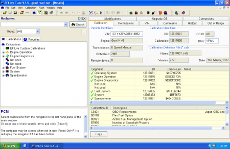
    • The Boxcode is typically a 3 or 4-digit letter/number code on the EEC computer. ( ‘A9L’  or ‘T4M0’ for example)  This represents a calibration for a particular engine/transmission using a particular strategy.
    • A Strategy is the set of procedures that the ECM follows to run an engine.  Combined with a calbration, this determines how the engine will operate.
      • The strategy will determine things like whether a MAF or MAP sensor is used, how spark and fuel are calculated, how idle is controlled, etc.
      • Each strategy needs a definition (or ‘def’) to work.  The definition tells the software how to interpret the binary and display it in a format you can understand with tables and real-world values.
      • For instance, the A9L boxcode, belongs to the GUFB strategy.  The A3M boxcode also belongs to the GUFB strategy.  You can change a bunch of parameters on a A3M computer and have it run 100% identical to a A9L computer.
  • Review your software options in terms of availability.
    • First: figure out which software supports your box code.  Support varies from package to package.  Check with each software vendor for the most up-to-date supported options.
    • Next: download software and install it.  You can check out the interface and features at this time without paying for anything.
    • Finally: After you have found a software package with an interface that you like which supports your strategy, go to our web store to purchase.  You will need to have already installed software prior to purchasing in order to provide us with information to license it.
  • Determine your tuning needs to guide your purchases.
    • Do you just need to burn chips?
    • Do you want to be able to make changes while the vehicle is running? (emulation)
    • Do you want to be able to log vehicle parameters while the engine is running? (datalogging)
    • Do you want a more accurate measure of the air/fuel mixture? (buy a wideband)
    • Decide what capabilities you need and then purchase hardware as appropriate.
  • Install hardware.
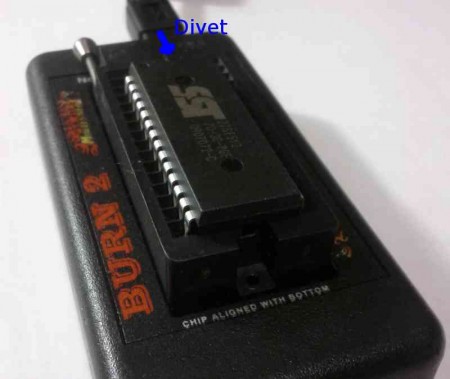
    • Clean that J3 port PROPERLY!
    • To clean the J3 port, you generally must remove the case from the ECM, gently rub the J3 port with Scotchbrite or a mildly abrasive kitchen scrubber.  (‘mildly’ is important – you do NOT want to rub hard enough to remove the copper traces from the circuit board!)  A final clean with brake clean, starting fluid  or another mild solvent doesn’t hurt.  A properly cleaned J3 port will have a very, very slight crosshatch visible on the ‘fingers’ of the connector.
    • Golden rule: ALWAYS TAKE THE KEYS OUT OF THE IGNITION (CAR OFF!!!)  WHEN INSERTING OR REMOVING THINGS ON THE J3 PORT. Failure to do so can result in a fried ECM, fried chip/QuarterHorse or both.
  • Install USB drivers
    • The same USB drivers are used for all Ford products
    • USB driver is a free download from the webstore, it comes with config instructions. (download)
    • If you need more visual directions, there is an install guide available on the Moates support site.
    • If you have trouble with the install, there is troubleshooting guide available on the Moates support site.
  • Setup software and perform initial configuration
    • Establish communications, check settings – this procedure will vary depending on software package you are using.
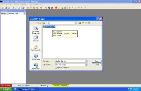
    • Select the appropriate strategy for your box code and load any appropriate definition files.
    • Program hardware with a calibration to serve as a starting point.  A stock tune with a few key parameters modified to suit the vehicle at hand is great.  You’re just looking for something good enough to get the car to fire and (hopefully) idle.
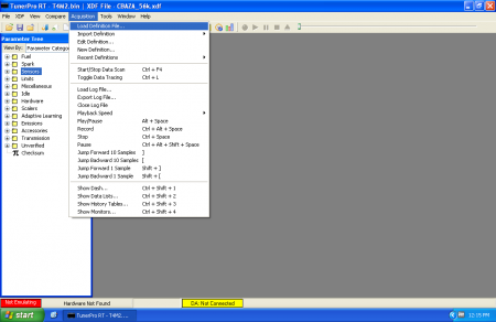
    • If you are datalogging, select and configure datalogging payload matrix (PIDs) – i.e. what you’re interested in monitoring.
  • Gather performance data, analyze it, and make changes toward an optimized result.
    • Parameters are gradually adjusted to achieve desired targets.
    • This is an iterative process, where adjustments are made and the results are evaluated followed by further adjustments.
    • Please see our subsequent chapters on Ford Tuning (available separately).
      • Basic Tuning Techniques and Common Examples
      • Advanced Tuning and Tricky Combinations

Chapter 2: Hardware Selection and Installation

Several types of hardware are available and needed depending on desired functionality.

Laptop PC

  • Windows XP/Vista/7 are all compatible with the Ford tuning software.
  • Something 5 years old or newer is recommended (no old 486 machines!).
  • Internet access is recommended to facilitate licensing and software installations.
  • USB ports (at least 1) are required. All needed cables are included with the hardware.
  • If logging wideband, a serial-to-USB converter may be needed. ($37 on our webstore – link)
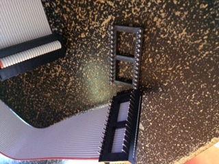
F3 Chip modules

  • These modules install onto the J3 port of the EEC box.
  • One per vehicle, $60 per unit – link.
  • J3 port MUST be thoroughly cleaned, both sides, before installation!
    • Disassemble case, scrape off coating with non-metallic scraper or fingernail.
    • Clean both sides with Scotchbrite, not sandpaper.
    • Don’t be too rough, just polish it to a nice crosshatch, not down to the copper.
    • Clean with paper towel and alcohol or toluene.
  • Two-position switch capable with user-added toggle.  Directions for switching are on support site.  (link)
  • Reprogrammable many times using Jaybird.

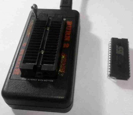
Jaybird mini-USB chip reader/writer

  • Small size, low cost, $75 – link.
  • Allows reading and writing of the F3 modules.
  • No datalogging or emulation with the Jaybird. No EEC box reading.  Most basic chip programmer available.

Quarterhorse Realtime Emulator and Datalogger

  • Hardware unit is $249 – link.  All cabling is included, along with ferrite shields and USB bulkhead connections.
  • Optional rotary switch ($30 – link) can be used to select from several different programs on the device, switching on-the-fly.  Works for EECIV ONLY.
  • Fits onto J3 port like a chip module –  port MUST be clean as with F3 modules.
  • On some early EEC boxes, several components will need to be gently bent out of the way for clearance during installation.
  • The Quarterhorse is an integrated unit that can do several things:
    • Realtime Emulation
      • Changes in the calibration take effect immediately while engine is running.
      • No disturbance in engine operation or communications.
      • Changes in software are synchronized on the Quarterhorse.
    • Datalogging
      • Requires special definition file with ‘patch code’ written for the QuarterHorse, allowing RAM on the EEC to be shadowed onto the Quarterhorse.
      • Unprecedented access to variables and sensor values through the QuarterHorse without additional datalogging hardware.
      • Logging rates in excess of 5 kHz possible.  Most software logs around 20 Hz, which is great for tuning.
    • EEC Reading
      • EEC must be installed and powered in-vehicle with QH installed.
      • You can read the tune from the EEC box and save it to file.
      • This can be done with a stock EEC to acquire the base calibration.
      • You will be able to harvest the active calibration that has been programmed with a flash programmer this way.

Burn2 with F2A and F2E adapters

  • The Burn2 ($85 – link) is a general purpose chip programmer that can be used for many different devices.
  • When used with the F2A adapter ($10 – link), it can be used to read/write F3 modules.
  • If the F2E adapter is added (another $10 – link), you will be able to read EEC boxes.
  • No emulation or datalogging – this is a simple chip programmer only.
  • This hardware combination is best suited for people that plan to tune vehicles from many different manufacturers.  If you plan on tuning exclusively Fords, consider the Jaybird as a less expensive alternative.

F8 chip module with Destiny programmer

  • No emulation or datalogging – this is a simple chip with switchable tunes.
  • Available exclusively through our distributor DP Tuner
  • The $165 F8 module holds 8 switchable tunes and can be reprogrammed in-vehicle without removing the chip from the EEC!
  • The $150 Destiny programmer is used with a 4-pin switch cable while F8 module stays installed on EEC.
  • Once programmed, the $30 rotary switch can optionally be connected as a calibration selector.

Wideband O2 Sensor and Controller

  • Used to sense your engine’s Air-Fuel ratio through exhaust gas analysis.
  • Units such as the Innovate DB-Red LC1 Gauge Kit /w/ O2 ($209 – link) are very affordable.
  • Software (discussed separately here) supports direct logging of the Innovate device data using a serial interface.  This is the preferred method of logging wideband data because it avoids all the pitfalls of using analog signals.
  • Analog outputs from the wideband (such as the LC1) can be connected directly to the EEC in some cases (unused EGR pin on A9L for example).
  • Wideband O2 readings critical for tuning fueling parameters.

Chapter 3: Software Selection, Installation, and Licensing

Several different software packages currently work with our hardware.  Cost varies considerably considerably from package to package along with capabilities.  Each software package also has its own unique flavor of interface – you will probably like one better than another.  Luckily, you can download and check them out prior to purchase.  Also remember that support for various box codes / strategies varies considerably from package to package.  It is important to investigate not just whether there is ANY support for a particular strategy but whether the items you require to tune your vehicle are supported – definition files vary considerably from software to software.  Fortunately, the availability of ‘trial’ versions makes it possible to ensure you to find a software package that fits your needs without having to purchase each one.

Binary Editor ( http://www.eecanalyzer.net )

  • Written by Clint Garrity.
  • Currently has the largest user base.
  • Cost is $80 for the base application which is registered to a specific PC.
  • Includes many of the most common and popular definitions (GUFB, etc) with no additional cost.  ( this list has almost all the “free” definitions along with some pay defs )
  • Other ‘premium’ encoded definitions available at extra cost ($50-150+) from the definition author.
  • Tends to benefit from a faster/newer laptop. Code is a bit heavy, so older PCs are taxed.  Think 2Ghz P4 / 512Mb ram realistic minimum.
  • Includes EEC reading, chip reading and burning, datalogging, and emulation capabilities when used with the appropriate hardware.
  • Also includes logging for wideband (Innovate, PLX, etc).
  • Also includes optional support for standalone dataloggers, J2534 interfaces.
  • Companion software EEC Analyzer is available for an additional $50. Not necessary, but it helps with data interpretation.
  • Licensing occurs after you install the software from the available downloads, through a menu item within the BE and EA software programs.
  • Both BE and EA licenses can be purchased from the webstore with information from the program.  See webstore product page for further instructions.

EEC Editor ( http://www.moates.net )

  • Written by Paul Booth.
  • Fairly lightweight software – does not require a very fast PC to work well.
  • Cost ranges from $20-65 for each strategy depending on options.
    • EEC-IV is $20 for editing DEF (emulation and chip burning) plus $25 for datalogging (DLM) .
    • EEC-V is $10 more ($30+$35).
    • In order to have a comprehensive tuning solution for a typical fox body Mustang, you would need to order the GUFB def ($20) and the GUFB DLM ($25) along with a QuarterHorse.  This would allow you to tune any number of vehicles using the A9L, A3M, etc. processor codes.  You can also burn chips with the Jaybird/BURN2+F2A for any strategies you have purchased.
  • Includes logging for Innovate Wideband (LC1, LM1, etc) at no additional charge.
  • List of available supported strategies is listed on the webstore.

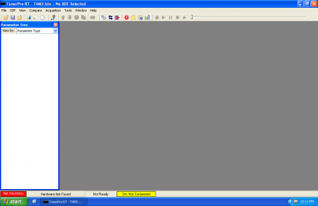
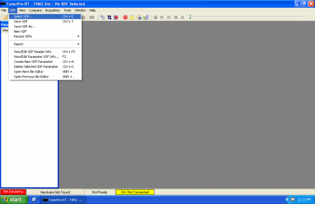
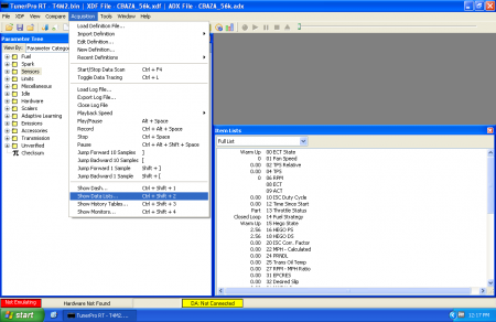
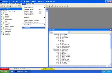
TunerPro RT v5 ( http://www.tunerpro.net )

  • Written by Mark Mansur.
  • Software license is optional (nag screen) but encouraged for $30.
  • Editing portion of software *extremely* lightweight – can run well on older PCs.  Parts of logging engine considerably more demanding.
  • Many definitions are available for editing only, see Tunerpro.net and our website for details.
  • Editing, chip burning and emulation are supported by TPRT V4 and TPRT V5.
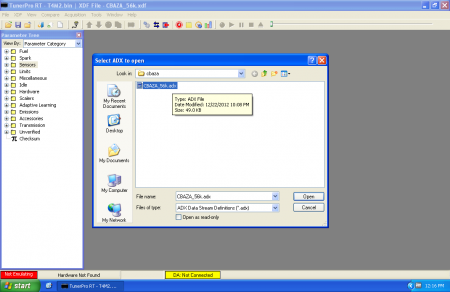
  • Datalogging using the QuarterHorse is supported by TunerPro RT V5 via new the ADX format.  See here for updated definitions.
  • QuarterHorse vehicle support is very limited compared to other software, but some of the most popular ones (GUFB CBAZA etc) are well-developed and available at time of writing (December 2010)

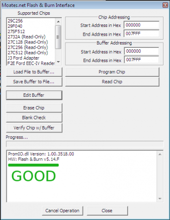
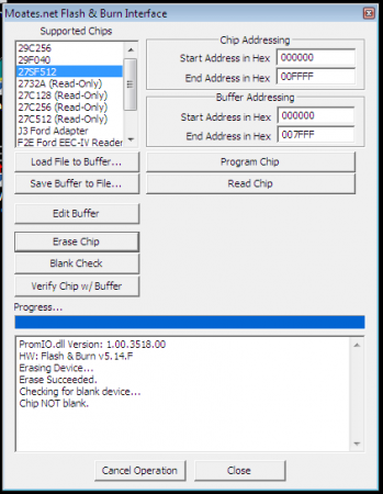
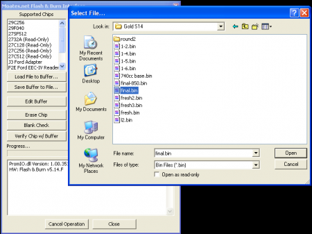
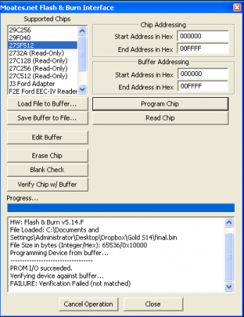
Flash & Burn Interface ( Moates/TunerPro )

  • This is a low-level utility for reading and writing F3 chip modules using Jaybird or  BURN1/BURN2 + F2A
  • Capable of reading EEC boxes using BURN2+F2A+F2E.  Does not work with QuarterHorse
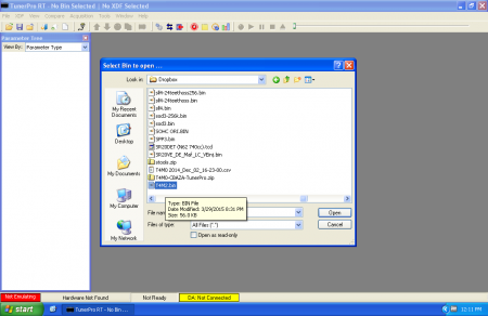
  • If you have a raw binary file ( bin ) you can use Flash n Burn to program a F3 chip module
  • No cost, can be downloaded from the webstore.

F8 Destiny Utility ( http://www.moates.net )

  • For use with a Destiny and F8 multi-position in-situ chip module.
  • Allows easy management of stacks of tunes on the module with PC-based selection.
  • No cost, can be downloaded from the webstore.

USB Driver ( Moates.net / FTDI )

  • Needed to allow PC to communicate with the USB hardware (Quarterhorse, Jaybird, BURN2, etc).
  • In many cases, working drivers will be detected by Windows via plug n play.
  • If you need more visual directions, there is an install guide available on the Moates support site.
  • If you have trouble with the install, there is troubleshooting guide available on the Moates support site.

Chapter 4: Suggested Techniques for Effective Calibration of EEC Systems

Vehicle Inspection and Preparation

  • CRITICAL part of the tuning process. Start here, really.  If you fail here, you will never succeed.
  • Several areas of the vehicle should always be analyzed before you begin the effort.
    • Smoking – learn to identify fuel (black) vs. oil (grey-blue) vs. coolant (white/sweet smelling).  You cannot fix oil smoke or coolant smoke with a tune.
    • Compression – you should have all cylinders within 10% compression of each other.  If smoking, damage to old spark plugs or general appearances make you suspicious of the motor’s health, check it before you start.  It’s a lot easier to deal with a motor with poor compression BEFORE you beat the snot out of it in the course of tuning it.  Many people skip this but it is something to think about because a motor that is already hurt is very likely to blow up or experience a catastrophic failure during tuning.
    • Check base timing, adjust as needed. (all vehicles with a distributor)
    • Evaluate TPS voltage.  Minimum/maximum values should be within acceptable limits.  Check for reversed wires – voltage should increase as throttle opens.
    • Look at MAF intake routing, make sure there are no obvious vacuum / intake leaks between the MAF and the intake valves.  Think cracked/split/loose hoses, bad gaskets, open ports, dry rotted couplers, hoses connected both before and after the MAF, …
    • O2 sensors should be operational without any exhaust leaks before the sensors.  For some reason, cut and soldered “extensions” for long tube headers often cause problems.  Plug and play extenders are *highly* recommended.  If you know that you do not have proper stock O2 sensors, REMEMBER TO TURN OFF O2 FEEDBACK!!!
    • If you are using a wideband sensor, you need to make sure there are no exhaust leaks before the wideband.  Flex tubing, poor joints between headers- midpipes and cracks in tubing can all create havoc.
    • If applicable, pay attention to which bank the wideband is installed in – bank-bank differences can be a powerful diagnostic tool.  Pay attention to how far the wideband is from the engine’s exhaust ports – there is always some lag between combustion events and measurement.  When things are changing quickly, this is critical.
    • Widebands need calibrated periodically, generally in free air.  Wideband sensors need replaced periodically.  Leaded fuel kills them very quickly.  Proper care and feeding of widebands is crucial to their effectiveness.
    • Be aware of catalytic converters.  Always tap them (GENTLY) and listen for suspicious noises that would indicate a catalytic converter that is degrading.  Clogged cats can rob literally hundreds of horsepower.  It is possible to place a wideband sensor AFTER a catalytic converter but remember that the cat will very slightly skew readings.
    • Make sure you have enough fuel pump and injectors for the power level you are looking for.  For a V8, “Injector size in #/hr * 14 = max hp” is a crude rule of thumb.  There are tons of injector calculators to be found if you want a better idea.
    • Ensure that fuel pressure is sane.  40psi with no vacuum reference is generally about where most OEM regulators are set.  You should be able to see a difference in fuel pressure between key-on-engine-off, idle and blipping the throttle.  Fuel pressure should be lowest when vacuum is highest.  Fuel pressure should increase when you blip the throttle as manifold pressure increases.
    • You need a MAF capable of metering enough air for your power goals.   There are ways to increase the metering capacity of a given meter, but tuning that properly is an advanced topic.  Keeping it simple: get a meter that can handle your airflow needs.
    • You need a functioning alternator and battery.  Battery voltage plays a role in crucial things like injector opening time and coil charge duration.  If your charging system is not functioning correctly, your tune may drastically change if/when you fix it.  Rule of thumb: if your battery voltage ever drops below 13 volts with the motor running, you will run into trouble.
    • On a similar note, underdrive and overdrive pulleys can cause real issues.  Pay attention if you see them.
    • Check for emissions hardware ( purge, smog pump, EGR, etc. ) that is missing.  In many cases these items can be disabled but you need to pay attention to what is present compared to what the ECM expects.
    • Basic maintenance should not be overlooked.  If it is important for a “normal” car it is twice as important in a performance application.
      • Spark plugs: correct heat range, appropriate gap, not fouled.  Consider power level, fuel and ignition system.  AVOID PLATINUM PLUGS FOR PERFORMANCE APPLICATIONS!!!  Copper or iridium will serve you much better.
      • Plug wires: no cracks/arcing, properly crimped ends, appropriate length so there isn’t too much tension
      • Firing order: firing order is determined by the camshaft (mostly) not the block or computer.
      • Spark boxes: great for distributor engines, unneeded/problematic for mod motors
      • Coil packs: Coil-per-cylinder (99-04 generally) applications like ***OEM*** coils best. (according to Dave B.)  MSD, Accel, Granatelli, … are all cause for concern especially with boost.
      • Oil and coolant: always check fluids before starting.  Quick check, potentially horrible consequences if low/out.
      • Fans / overheating: it is always a good idea to check that radiator fans work.  A car that overheats cannot be tuned.
      • Belts and Idlers: All serpentine belts must be in good shape.  Cracks, missing ribs, etc. will all cause problems.  Any idler pulleys must spin freely.
      • Tension:  Belt Tensioner should not be extended fully with the engine off.  Adjust belt length so that tensioner is in the lower third of its adjustment range with the motor off.  (i.e. it can move 2/3 through its range to increase belt tension – it should be mostly compressed when motor idle)  This is particularly important for supercharged applications.
      • Fuel filter: Fords are *horrible* about clogging fuel filters.  Especially if the car has been sitting for any significant period of time, change the fuel filter.  Motorcraft/OEM filters seem to hold up better than many cheap aftermarket ones.
      • Fuel age and type: Gasoline degrades with time.  Do not expect fuel that is more than a month or two old to be of the same quality as fresh gas.  Be particularly careful with heavily oxygenated fuels (i.e. VP Q16) and alcohols (ethanol, methanol, E85, etc.) in contact with fuel system components for large periods of time.
      • Clean air filter and MAF.  Oiled filters generally cause MAFs to get dirty.  Clean MAFs only after they have had a long time to cool – hot MAF+liquid=death.  Clean *GENTLY* with brake clean, starting fluid, or other organic solvents.
  • Remember, you can’t fix mechanical or electrical issues by reprogramming the ECM!!! The results you achieve with tuning will only be as good as the material you start working with.  Garbage in, garbage out.

Datalogging: What’s important and what does it mean? What should we be interested in? What to select?

  • There are certain sensors that you will almost always want to keep an eye on because they are critical to engine operation:
    • RPM – how fast the motor is spinning
    • MAFV / MAF counts – a “raw” value representing the reading from the MAF sensor
    • Airflow – a value calculated  by the ECM from the raw sensor MAF voltage that represents how much air is being ingested by the engine.  This is often represented in some form of “real world” value, like Kg/hr or Lbs/min
    • Load – from 94-2004 “Load” is the main factor involved in determining spark advance.
    • Spark Advance – when the ECM is commanding sparks to be fired.
    • TPS – Throttle Position Sensor.  How far open the throttle is, i.e. how hard you’re pressing the gas pedal
    • ECT – Engine Coolant Temperature(how hot or cold coolant flowing through the engine is)
    • IAT – Intake Air Temperature (how hot or cold air entering the engine is)
  • Depending on what you are trying to do, there are other items you may want to pay attention to as well.
    • Injector Pulsewidth – How long the injectors open.  This can be useful both for “sanity checking” and to ensure you do not run out of injector – there is only a fixed time available at a given RPM to fire injectors.
    • HEGO1/2 – Heated Exhaust Gas Oxygen sensor.  Measures the presence or absence of oxygen in the exhaust in order to try to determine whether the motor is running rich or lean.   Watching the raw HEGO voltages can give you some kind of very basic indication of fueling.  These sensors experience a large change in voltage in a very small area centered around a stoichiometric mixture ( 1.0 lambda or about 14.7:1 Air-Fuel Ratio or AFR)
    • STFTs – Short Term Fuel Trims.  These are IMMEDIATE changes the ECM makes in response to HEGO readings in order to steer the air-fuel mixture towards desired targets.   If your EEC uses STFTs effectively (i.e. all modular motors) then these are generally more effective as a tuning tool than looking at raw O2 voltages.
    • LTFTs – Long Term Fuel Trims.  These are the long term difference between programmed values and target values.  Think of them as the average of STFTs over a long time.  If your EEC uses LTFTs effectively (i.e. all modular motors) then these are one of the most effective pieces of data provided by the stock computer for tuning fueling.
    • WBO2 – Wideband Oxygen meters can measure a much wider range of rich-lean conditions than standard HEGOs.  Having wideband data is often preferable to HEGO/STFT/LTFT.  In many cases (i.e. 86-95 in my opinion) it is often easier to disable closed loop operation/the O2 sensors completely and tune the car exclusively using a wideband.
    • ISC Integrator (‘integrator’) – this represents the difference between how much air the EEC is using to hold and idle versus how much it is commanded to hold in the tune.  Critical for proper tuning of larger camshafts and larger displacement engines.
    • Boost/MAP/Pressure – Although MAF systems do not differentiate between boost and vacuum, it is often very handy for sanity and safety to have an idea of how much pressure there is in the intake manifold.  For positive displacement blowers (roots, TVS, twin-screw) make sure you take pressure readings AFTER the blower on the lower plenum.
    • Pressure drop across injectors / FPDM duty cycle – most 99-04 cars control fuel pressure electronically.  These values are critical to a properly operating fuel system on these vehicles.

Recalibration: Modifying Parameters and Values to Achieve a Target

  • First step: decide on target operating parameters for the engine
    • This may seem obvious, but something as simple as “make the most power” or “improve fuel economy” isn’t going to be be enough.
    • Second step: take a general goal like “make the most power” and decide on appropriate engine conditions to achieve that goal.
    • If you read these rules of thumb and say “this isn’t right for my engine” – GREAT.  You already know more than the audience these rules are aimed at.
      • If in doubt, “0.8 is great” – blatant simplicity.  Quoted me to once by someone who did OEM calibrations for Honda for a living.  It is very difficult to break anything due to fueling from running a vehicle at 0.8 lambda (about 11.6:1 AFR Gasoline)
      • 1.0 Lambda represents a stoichiometric mixture – exactly enough oxygen is present in the air to burn all the fuel supplied.  This is normally the best mixture for minimizing emissions.
      • Most vehicles make best power around 0.85 to 0.88 lambda (12.3 – 12.7 AFR Gasoline) – slightly richer than stoich
      • Most vehicles achieve best fuel economy at around 1.05 to 1.1 lambda ( 15.2 to 16.0 AFR gasoline)
      • Most vehicles need more ignition advance as RPM increases
      • Most vehicles need more ignition advance under cruising/low-throttle conditions than WOT
      • Knock is most likely close to peak torque, at high loads/low RPMs or at peak horsepower
  • Next step: Get familiar with the strategy your vehicle uses.  Fueling, timing, idle, open-closed loop and just about everything else vary considerably from one strategy to another.  Being familiar with the strategy your ECM uses will help you figure out which tables to modify to acheive the results you seek.
    • eectuning.org is a good place to learn more.
    • the ‘Education’ section of moates.net is another good place to get information
  • After you figure out where to look: set up what you can based on what you already know
    • Setup Engine Displacement / displacement of one cylinder
    • Setup injector size
    • Setup a reasonable rev limiter based on what you know of bottom end and valvetrain
    • Setup a reasonable (perhaps a little high to start) value for target idle
    • Setup a reasonable base calibration for MAF sensor.  If sensor came with a calibration sheet, this would be great time to use it.
    • Setup a reasonable target air fuel while in open loop
    • Setup a reasonable timing map.  A stock timing map adjusted for mods is always a good place to start.
    • Setup a reasonable pattern from switching from closed loop to open loop.
    • Enable or disable hardware such as O2 sensors, EGR, Purge/Evap, automatic trans
    • If you take your time to create a sane starting point before you turn the key on you will save yourself countless hours of time!
  • Finally: Start your engines (and your datalogger) and make final adjustments
    • Are air fuels not matching what you command in open loop?
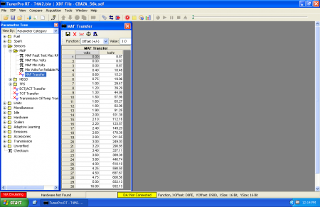
      • Three pieces of the fueling puzzle:  MAF transfer, Injector slopes(size), Injector offset (battery compensation – latency)
      • How do you tell what is going on?  STFTs, LTFTs (if O2s are enabled) combined with a wideband.  STFTs/LTFTs are great while O2s are active – i.e. part throttle
      • Leanest at idle, small pulsewidths but perfect at WOT/higher throttle -> increase battery offset
      • Lean – rich – lean patches as you gradually increase throttle -> wrong shape of MAF curve.  systematically tune it
      • Entire range of engine operation uniformly off from commanded values -> either injector slopes (size) or entire MAF transfer function is off.  Let load determine which one to multiply/divide in order to fix things
    • Idle issues?
      • Make sure your MAF transfer table, injector slopes and injector offset are sane before trying to fine tune idle!
      • Follow the integrator – a good place to start is to add the integrator (or subtract if it is negative) from the Neutral Idle Air table (in neutral) or Drive Idle Air table (if in Drive for automatic cars)
    • Performance
      • ALWAYS TUNE FUELING FIRST BEFORE TACKLING TIMING!  You are *much* more likely to break your engine if your mixture is wrong.  As long as your timing is good enough to light the mix, you can tune fueling adequately.
      • Tuning timing without a dyno is hard.  Accelerometers and a dragstrip can provide crude but repeatable feedback.

Data Analysis and Evaluation

  • Once captured, the operational data can be analyzed and used to guide calibration effort.

(More to come!)

(below this line is draft / coming soon as of 2010-11-30)

Chapter 4:  Software/Hardware Initial Configuration with Tuning Session Start-Up Examples

  • Physical installation of hardware is shown in more detail from Chapter 1 overview.
    • F3
    • Jaybird
    • Quarterhorse
    • F8/destiny and switch
    • Wideband
  • Installation, licensing, initial configuration, and detailed hardware synchronization procedures for each software are explained and examples detailed. Initial basic calibration load-up for different hardware, as well as basic payload creation for datalogging, are explained and illustrated for each.
    • USB Driver
    • BE/EA
    • EEC Editor
    • TunerPro RTv5
    • Flash & Burn
    • F8/Destiny Utility
  1. Data Analysis and Evaluation
    1. Once captured, the operational data can be analyzed and used to guide calibration effort.
    2. Several examples of logged data values and how they relate to calibration parameters are provided.

Chapter 6:

Case Studies: Example Modifications, Vehicle Combinations, and Rules of Thumb

  1. Key Issues and Vehicle-Specific Examples
    1. How do many of the popular modifications on these vehicles affect the tuning approach?

i.      Bigger MAF

ii.      Bigger injectors

iii.      Cold plugs

iv.      Nitrous

v.      Gears and converter

vi.      Auto vs Manual

vii.      Emissions delete / racing modifications

viii.      Cam, heads

ix.      Headers/exhaust

x.      Cold air intake

    1. We look at a walk-through of important considerations and the thought process of tuning several different example combinations, with real-world dyno results.

i.      A9L/GUFB Fox Body, 1993 N/A 331 stroker, 24# injectors, cam, headers, 5spd.

ii.      CBAZA, same as above.

iii.      03/04 Mustang

iv.      SC A9L

v.      SC 03/04 Cobra

vi.      F150 Truck

    1. Achieving an Optimized Result: When is it good enough?

i.      What are your goals?

ii.      Do you plan for future modifications?

iii.      Rules of thumb for AFR and timing, NA vs boost.

iv.      What is safe vs aggressive?

>

>

>

> Vehicle Compatibility

>

> All year/model Ford 2004 and earlier with J3 port are compatible

***with our hardware*** but there may not be software support for particular models.

> Some vehicle year/model applications are simply not supported in the

> software because of lack of definition information. It’s important to

> evaluate the availability of your desired application as ir relates to

> the software selection process. You may be out of luck (for example,

> 1995 Festiva or such uncommon target).

http://support.moates.net/ford-strategies-supported/

http://support.moates.net/ford-box-code-strategy-cross-reference/

>

>

>

> Overview of Tuning Process

>

> Determine your target vehicle boxcode and strategy

>

>                                                                i.

> Boxcode is typically a 4-digit letter/number code on the EEC computer.

> This is the calibration code.

http://support.moates.net/ford-information-we-need-to-help-you/

>

>                                                               ii.

> Strategy is the ‘parent’ definition structure to which a boxcode belongs.

Each strategy is the set of procedures that are executed on your ECM to run an engine.  Sometimes more than one strategy can successfully run on a given ECM.  Normally we do not make many changes to the procedure part of strategies while tuning vehicles.  Instead, we change tables, functions and constants so that the engine receives what it needs to run well.  Each “box code” represents a configuration of a particular strategy for a particular engine.

>

>                                                             iii.

> For

instance, the A9L boxcode  belongs to the GUFB strategy.  The A3M boxcode also belongs to the GUFB strategy.  If you compare A9L.bin and A3M.bin the files will be almost identical because they use the same strategy but are configured for different vehicles by Ford.  If you get a definition (also called def) for the GUFB strategy, you will be able to edit both A9L and A3M binaries because they use the same strategy.

……….

>                                                             iii.

> J3 port MUST be thoroughly cleaned, both sides, before installation!

***IMPORTANT***

……………….

> Chapter 5:

>

> Suggested Techniques for Effective Calibration of EEC Systems

>

>

>

>

>

> Vehicle Inspection and Preparation

>

> CRITICAL part of the tuning process. Start here, really.

> Several areas of the vehicle should always be analyzed before you

> begin the effort.

>

>                                                                i.

> Check base timing, adjust as needed.  On older Fords, pull “spout” timing connector either by distributor (86-93) or on passenger fender side (94-95).  Adjust distributor to achieve 10 degrees base timing with spout removed.  Reinstall spout before tuning.

>

>                                                               ii.

> Evaluate TPS voltage, make sure it is in range through motion.

Vehicles are very sensitive to improper TPS voltage.  TPS being too low or too high can cause the ECM to not enter the correct idle mode.

TPS should be between 0.95 and 1volt with throttle plate closed.  This can be checked using QH quite nicely.

>

>                                                             iii.

> Look at MAF intake routing, make sure there are no gross vacuum / intake leaks.

http://support.moates.net/tuning-maf-systems-and-air-leaks/

See how much or little of that you want to put here.

>

>                                                             iv.

> O2 sensors should be operational, exhaust should be leak-tight at

> least that far back.

OEM Ford O2 sensors work a million times better than cheap aftermarket ones.

Ideally, a wideband sensor is to be installed in addition to the factory O2s rather than instead of one.

If this is not possible, it is greatly preferable to remove a secondary (Post-catalytic converter) O2 sensor.

If a primary O2 sensor has the be removed in order to install a wideband, make sure closed loop operation is disabled.

>

>                                                              v.

> Basic maintenance should not be overlooked.

>

> 1.       Plugs and wires

1a. PLUG GAP IS REALLY IMPORTANT

1b. Appropriate plug type is really important (Copper, Silver (Brisk for 3v)).  Iridium plugs are ok for applications with extremely strong spark boxes or CDI systems.  Avoid platinum plugs like the plague.

>

> 2.       Oil and coolant

>

> 3.       Fuel filter and fuel age/quality/octane

>

> 4.       Clean air filter and MAF

>

>                                                             vi.

> Ensure that fuel pressure is as expected through operating range.

>

> Remember, you can’t fix mechanical or electrical issues with reprogramming.

> Tuning is about more than just flipping chips, so make sure your

> vehicle is in good shape!

This really can’t be stressed enough.  Tuning a car that isn’t running right is like putting a bandaid over a gangrenous wound!  The first step to tuning a car properly is to make sure it is mechanically sound!

>

>

>

************I’m not sure I would get into datalogging just yet because we haven’t talked about recalibration yet.****************

> Datalogging: What’s important and what does it mean? What should we be

> interested in? What to select?

>

> RPM

> MAFV

> Kg/Hr

> Spark

> HEGO1/2

> TPS

> ECT,IAT

> Load

> WBO2

>

***********************************Snip*********************************************************************************************************

>

>

> Recalibration: Modifying Parameters and Values

>

The purpose of recalibrating an ECM is to produce the behavior you desire, and by doing so hopefully improve performance, emissions or other operating characteristics.  Normally, there are two stages to this process.

First, parameters within the strategy are altered to match physical parameters of the engine.  Engine displacement, injector size are the primary values here.  Also, the MAF transfer function should be altered to match the MAF that is installed on the vehicle.  You can often “rob” a MAF transfer function from another vehicle’s strategy when using the MAF from another vehicle.

Next, operating parameters are changed in order to achieve the actual running conditions desired for the particular engine.  In many cases, simply adjusting the “configuration” items for the strategy in the first step will make then engine run great but there are almost always small changes that can be made to optimize performance.

>

> What are the most common values we will need to modify?

>

i.     Displacement – how large the engine is

ii.      Injector slopes – define how much fuel flows through

injectors, aka injector size

iii.      MAF calibration – defines how much air enters the engine as

a function of MAF voltage.  aka MAF transfer function iv.      Rev limiters – protect the engine from being damaged by over-revving

v.      Speed limiters – protect the driver from his/her own stupidity

vi.      EGR delete, PATS delete, secondary O2 delete – turn off items that are not present or not desired.

>

> How do we know which values to change, and by how much?

>

(repeat / correlate with above)

First step: calibration data should match actual equipment specification

example: If you have a 347 stroker with 30# injectors your strategy should be configured to match these physical parameters

Next step: start your engines, identify problems and goals.  There are hundreds (if not thousands in some cases) of parameters you can change.  Before starting on tuning, it’s good to have an idea of what’s not right, what you’d like to improve and what you can leave alone.  This may sound basic, but maintaining some kind of focus is really important to working effectively.  Examples of things you might want to work on are improving idle, improving wide open throttle performance, decreasing fuel consumption.

After figuring out what aspects of running the engine you want to work on, it is time to get the data you need to achieve your goals.  By selecting appropriate items for datalogging, the QuarterHorse allows you to view, log and replay the same data that your ECM uses to run your engine.  Instead of blindly guessing which values you need to change in order to get the engine behavior you seek, you can use this process of logging, analyzing logged data and a little math to make appropriate changes.

Now specific tasks in the tuning process will be examined in detail.

This will be presented as a mixture of theory and practice.  The next chapter will serve as a guide for how to adapt the programming of your ECM to suit specific modifications (cold air kits, injectors, motor transplants, etc) and will be attempt to be primarily hands-on.

Routine tuning processes: (these are going to need more explanation, I’m just running out of steam tonight)

Basic setup – Slopes, injectors, MAFs, sane spark tables

WOT / Open loop fueling – MAF transfer, inj slopes, stabilized fuel table

Closed loop fueling – O2 trims, MAF transfer

Power tuning – Dyno, spark tables

Idle tuning – idle RPM drive, neutral, Drive idle air, neutral idle air, integrator, gains, etc

Dashpot – role, tuning, scalars, preposition

>

>

>

> Chapter 6:

>

CASE STUDIES AND HANDS ON PRIMARILY.  Theory / processes in previous chapter

>

>

>

>

>

> Key Issues and Vehicle-Specific Examples

*MAKE MORE SPECIFIC*  General procedures covered above

>

> How do many of the popular modifications on these vehicles affect the

> tuning approach?

>

>                                                                i.

> Bigger MAF

>

>                                                               ii.

> Bigger injectors

>

>                                                             iii.

> Cold plugs

>

>                                                             iv.

> Nitrous

>

>                                                              v.

> Gears and converter

>

>                                                             vi.

> Auto vs Manual

>

>                                                           vii.

> Emissions delete / racing modifications

>

>                                                          viii.

> Cam, heads

>

>                                                             ix.

> Headers/exhaust

>

>                                                              x.

> Cold air intake

>

> We look at a walk-through of important considerations and the thought

> process of tuning several different example combinations, with

> real-world dyno results.

>

>                                                                i.

> A9L/GUFB Fox Body, 1993 N/A 331 stroker, 24# injectors, cam, headers, 5spd.

>

>                                                               ii.

> CBAZA, same as above.

>

>                                                             iii.

> 03/04 Mustang

>

>                                                             iv.

> SC A9L

>

>                                                              v.

> SC

> 03/04 Cobra

>

>                                                             vi.

> F150 Truck

>

> Achieving an Optimized Result: When is it good enough?

>

>                                                                i.

> What are your goals?

>

>                                                               ii.

> Do you plan for future modifications?

>

>                                                             iii.

> Rules of thumb for AFR and timing, NA vs boost.

>

>                                                             iv.

> What is safe vs aggressive?

>

>

Install USB drivers, Configure software, synchronize it with the hardware via USB, and load up initial calibration.
Establish communications, check settings.

BURN1+F2A+F2E: Reading Ford ECMs

Requirements

There are two products that we sell that can read the program in a factory ECM:

BURN1/BURN2 with a F2A and F2E – This setup can be used to read ECMs on the bench.  ECM does not need to be powered.

QuarterHorse – This setup requires the ECM to be powered either by a vehicle’s battery or a 12V bench power supply.

Reading with BURN2+F2A+F2E

  1. Start with all cables disconnected (F2A,F2E,USB,etc.)
  2. Connect the F2E to the F2A
  3. Put the F2A in the BURN1/BURN2
  4. Connect the Burn1-2/F2A/F2E Assembly to your ECM.  Make sure your ECM is powered off if it is in the vehicle
  5. Connect the USB from the BURN2 to the PC
  6. Start Flash n  Burn Software on the PC
  7. Choose appropriate settings for the Supported chip type based on the ECM type:  J3 Ford EEC-IV Reader or J3 Ford EEC-V Reader
  8. Choose appropriate settings based on the number of banks used:
    • 56k EEC-IV = 032000 start 03FFFF end
    • 64k EEC-IV = 030000 start 03FFFF end
    • 2-bank EEC-V = 010000 start 02FFFF end
    • 4 bank EEC-V = 000000 start 03FFFF end
  9. Click “Save buffer to file” and choose a filename.

Reading with QuarterHorse

At the time of writing (Aug5-2010) Binary Editor is the only software that supports this feature of the QH reliably.  Select “Read PCM” from within the software.

Ford Tuning: Load with failed MAF table(s)

Introduction / Prerequisites

Before you read this, make sure you have read Theory: Alpha-N, Theory: Mass Air Flow and the FordOverview.  Although not essential, it wouldn’t hurt to have at least read about Speed-Density operation as well.  This page will assume you have read and understood these pages.  This is a somewhat complicated topic and will require you to put several pieces together so don’t feel bad if you have to read this a couple times.

About the table and why it is critical

The “Load with failed MAF” (“LWFM” from here forward) table(s) are found in almost all MAF Ford Strategies.  Most strategies that make use of IMRCs (Intake Manifold Runner Control – valves that restrict air entering the engine in order to increase tumble and velocity) have two LWFM tables instead of one and  switch from one LWFM table to the other as the IMRCs open and close.  The main purpose of the LWFM table is to estimate the amount of air going into the engine without using the MAF sensor or a MAP sensor (if present) to provide the ECM with an “emergency” fallback method of running the engine in the event the MAF sensor fails.

The LWFM table is also important for normal operation of the motor because Load from the MAF (this is “Load” – the Ford-specific calculated cylinder filling value calculated from the MAF sensor, RPM and engine displacement) is “sanity checked” against the LWFM table to determine if the MAF is providing reliable information.  If there is too large of a difference between calculated Load and the LWFM table, the ECM may ignore the MAF even if it is providing valid information! This happens most commonly in forced induction situations (where load is greatly increased compared to a naturally aspirated car) but can also occur in cars with aggressive camshafts.  If you are making changes to a MAF transfer function and you are not seeing any changes in engine operation, double check your LWFM table!  Further, most strategies use “Anticipation logic” to predict airflow.  This prediction logic is based off…  Surprise… The LWFM table!  Having a sane LWFM table is neccesary for the aircharge anticipation logic to work.  You can disable this but it’s generally not necessary if you tune the LWFM table properly.

LWFM table is a classic example of an Alpha-N control strategy – it’s purpose is to provide a very crude estimation of airflow entering the engine when the MAF signal is absent or the ECM thinks it is unreliable.   The LWFM table uses only two inputs – throttle position (aka “TP”) and RPM to determine Load.  Here is a picture of a typical LWFM table: (screenshot from Binary Editor / GUFB strategy)

Here you can see the X axis is RPM and the Y axis is RELATIVE Throttle Position volts.  Each cell represents the Load that will be used to calculate fueling and timing when the ECM thinks the MAF is bad.  For example, idling with the throttle closed (0 volts relative)  around 700 RPM the ECM will assume a Load of .1602 and make appropriate fueling and timing changes.

The importance of the LWFM table varies considerably from strategy to strategy.  A rule of thumb is that the newer of an ECM you are using the more picky it will be able the LWFM table.  Fox Body and most early EECV (pre-99) are fairly tolerant of inappropriate LWFM tables where 99+ ECMs are generally much, much, much more picky.

Tuning the LWFM Table

Tuning the LWFM table is pretty simple:

First, set the Aircharge WOT multiplier, Anticipation logic scalars, etc. to make the ECM as tolerant of a bad failed MAF table as possible

Second, GUESS!   Yes, guess.  Enter values that you think are sane for the setup, starting with the stock LWFM table as a guideline.  A few examples:

  • If you put in aggressive cams, decrease the LWFM table at low RPMs and throttle angles while increasing it at higher RPMs and throttle angles.
  • If adding a positive displacement supercharger (roots, twin screw) multiply the whole LWFM table by approximately the highest pressure ratio you will see.
  • If you add a centrifugal blower, multiply a column of the LWFM table by the pressure ratio you achieve at a given RPM

Third, drive around and log throttle position (TP Relative), RPM, Load.  Compare the Load values you log with the LWFM table.  Start changing entries in the table so they get closer to the load you really see at given TP and RPM conditions.

Note: Turbo cars present a very big challenge to this strategy due to the amount load can vary with throttle position due to spool time.  This is a very tricky case and often the only solution is to try and maximize allowed error before the LWFM table becomes active and also disable Aircharge Anticipation and other functions dependent on the LWFM table.

Tuning: MAF systems, air leaks and reversion

Introduction

As stated in our overview of MAF systems, one of their main weaknesses are air leaks.  Whenever air can enter the engine without going through the MAF, weird things happen.

There are two principal kinds of leaks that wreak havoc on MAF systems – constant leaks (like a unplugged vacuum port) and mechanically induced leaks (such as a Blow Off Valve or Bypass Valve that vents to atmosphere.)  Each leak has a tendency to affect the system differently.  In this article, we will try to take a look at what “should” be happening, what changes with a leak and what kind of odd things you can look for while tuning to identify a leak.

Reversion presents an additional problem for MAF systems.  Reversion is the technical name for when air changes direction and reverses flow.  MAFs are not one way systems – they will measure air flowing into the engine and then meter the same air flowing out of the engine when there is severe reversion, causing unreliable MAF readings.

Constant leaks

This kind of constant leak in a MAF system is the classic “vacuum leak” where a gasket, coupler or piece of tubing in between the MAF and the engine does not seal properly.  In this case, air can enter the engine without passing through the MAF.  Because air has entered the engine without passing through the MAF sensor, the MAF sensor reads artificially low.  An engine operating in open-loop mode will tend to run very lean.  A motor operating in closed loop will see very large positive trims as the computer uses the O2 sensors to add fuel to compensate for the lean condition.

The air leak provides more air for the engine at idle which will make the idle rise or sometimes “hunt” or bounce around unstably.  Generally, the idle system will also try to compensate.  On Fords you will see the ISC Integrator (“Integrator”) swing negative, indicating the ECM is allowing less flow through the idle valve than is commanded in the tune.  It is very common for the Integrator to get stuck at the minimum allowed value and have the car still idle higher than commanded.

Most MAF systems use the MAF for calculating appropriate timing values as well as fueling.  With a vacuum leak throwing off the system, the ECU thinks there is less air entering the engine than their really is.  This will mean that “load” values will be artificially low, which generally leads to timing being artificially high.  In severe situations, this combination of issues (less fuel, more timing) is a recipe for melting engine components if it goes unchecked.

Mechanically induced leaks

Bypass valves are the most common source of mechanically induced leaks although idle, purge and other vacuum operated solenoids can all be a problem.  MAF systems require these valves to be re-circulated so that air leaving the valve re-enters the intake AFTER the MAF so it does not get measured twice.

Blow off valves on turbocharged vehicles are often vented to atmosphere.  This unfortunately will severely confuse a MAF system.  When the valve opens, air that has already passed through the MAF and been “counted” is released into the atmosphere instead of entering the engine.  The ECU will supply enough fuel for all the air that has passed through the MAF while only a small portion of this air actually entered the engine.   This causes the engine to run very rich and can cause stalling or other problems when letting off the gas and the BOV opens.  Once the valve closes again and the car burns off the excess fuel delivered, things slowly return to normal operation.

Supercharger bypass valves can present the same kind of issues when they are allowed to vent to atmosphere. (or when there is a leak in the piping allowing air to recirculate.)  Failing to catch an air leak with a supercharger bypass will result in the MAF curve having a sudden change when the valve closes.  This will require complete re-tuning of the MAF transfer function once fixed so it is best to catch it early.

Reversion

Reversion is most common in engines with very large camshafts operating at low speeds such as close to idle.  Situations where MAFs read unreliably due to reversion can generally be greatly improved by moving the MAF further from the throttle body.  Increasing the volume of the intake between the MAF and the throttle body is also effective at smoothing out the pulses of air coming from an engine with a radical camshaft.  It is normally possible to get a reliable enough MAF signal in most circumstances.  Even extremely wild cams that draw 3-4″ of vacuum at idle can be tamed with an appropriately designed intake system.

Another form of reversion that is troublesome to MAF systems happens with poorly designed supercharger bypass valve systems.  In most of these systems, the pipe connecting the outlet of the bypass valve connects with the inlet of the supercharger at an angle where recirculated air flows backwards through the intake.  This causes any reverse-flowing air to be metered multiple times by the MAF, leading to unreliable operation.  This can almost always be remedied by adjusting the angle of the pipe from the bypass so it points at the inlet of the supercharger directing the flow of recirculated air away from the MAF.

Reversion is very obvious if you are logging the MAF signal. Looking at a graph of a “normal” MAF signal versus time, it will look like a line that could have been drawn without reversing the direction of travel.  The same graph of a MAF impacted by reversion will look very “shaky” and jagged, changing direction many times in a short period of time.

Ford: Box code – strategy – vehicle cross reference

This page is intended to help people who have looked here to figure out if there is support for their vehicle.

Each ECM has a 3 or 4 digit processor code that uniquely identifies it.  You can tell what strategy a ECM uses from its box code or from looking at a dump of a stock program from that ECM.  “Strategy” is Ford’s lingo for a program to run a vehicle. (or operating system)  Each strategy can have multiple calibrations for different engines.  Sometimes even V6 and V8 engines will use the same strategy!

If you are wondering if your strategy is supported, take a look at the Supported Strategies guide.

This list will grow over time.  If you don’t see your vehicle listed here, email [email protected]

A9L = GUFB (88-93 “Fox body” V8 mustang 5-speed)

A9P = GUF1 (88-93 “Fox body” V8 mustang auto)

T4M0 = CBAZA (94-95 SN95mustang  5.0 V8)

LLX4 = CDAN4 (96-97 Cobra 4.6L 32v)

PTP2 = FBFG2 (04 Mustang GT)

RCX5 = CDAN4 (97 Tbird 3.8L v6)

SLL4 = CTBAE (96 5.0 explorer ??? )

LKT3 = ODAJ0 (02 F150 4×4 auto)

SCI1 = ODAG0 (02 F150 4×4 manual)

NMI1= ODAG0 (02 F150 4×4 manual)

MIJ1 = ODAG0 (02 F150 4×4 manual)

KVF1 = ODAL1 (02 F150 4×4 manual)

CXN1 = MNAE1 (01 Lightning)

CUX1 = MRAD2 (01/02 Lightning)

CUX2 = MRAD3 (01/02 Lightning)

URB1 = TAUF0 (02/03 Lightning)

There is a handy Excel spreadsheet you may want to look at ( link ) that has a decent cross-reference.

External Resources

Core Tuning have an excellent list of strategies they support which can be used to cross reference ECMs and strategies.

OBDTester.com has a nice list of Ford ECM info organized by hardware ID and updates for Ford ECMs.


Who uses our gear?

This page is being created so we have a place to keep track of all the people who are using our gear for various applications.  If you would like to be added or removed from here, please email [email protected] or leave a comment.  Hit control-F to find keywords on this page as eventually we hope this grows to a very large list!

ECU Connections forum – mostly Bosch Motronic stuff.

DS-MAP – MAP sensor conversion for DSM ECUs, supports Ostrich

TunerPro RT – general purpose ROM editor that supports APU1, Ostrich, ALDU1 and most of our gear.  Useful for Nissan, Ford, GM, DSM, some Bosch Motronic (BMW, Porsche, VW, etc.) among others. (we sell this)

ThirdGen.org – forum dedicated to the 3rd gen camaro/firebird with a great Tuning section!

EFI Live – Supports our RoadRunner Emulator for OBD2 GM vehicles (we sell this)

Binary Editor – Supports our QuarterHorse emulator for 86-04 Ford vehicles (we sell this)

EEC Editor – Supports our QuarterHorse emulator for 86-04 Ford vehicles (we sell this)

TunerCat – supports APU1, ALDU1, Ostrich, etc. for OBD1 GM vehicles

Neptune – supports Demon, Ostrich, BURN2,  etc.  The premiere solution for tuning 92-01 distributor Hondas (we sell this)

eCtune – supports Demon, Ostrich, BURN2, Hondalog, etc.  Another great 92-01 distributor Honda solution

Crome – supports Demon, Ostrich, BURN2, Hondalog, etc.  an older and poorly maintained 92-01 distributor Honda solution

TurboEdit – supports Ostrich, Hondalog.  an old and finicky software package for 88-91 distributed Hondas

BRE – supports Ostrich, Hondalog.  an old and finicky software package primarily aimed at 89-91 Vtec hondas

Pgmfi.ORG – Home of the DIY Honda community.  Birthplace of CROME, TurboEdit, BRE and loosely affiliated with other softwares.  Still a great resource for Honda ECU tuning.

Nistune – supports Ostrich, dual Ostrich.  Nissan ROM tuning software, dealer version works with our hardware.  Programs made with Nistune work with our Nissan 2Chip adapter.

Tuning Porsche 944 turbo vehicles using TunerPro, Ostrich, SocketBooster (thanks Joshua)

Turbo Mopars using Ostrich2

RhinoTuning using Ostrich2 / BURN2/ etc. for tuning Suzuki Swift pre-OBD2 vehicles

Nissan Data Voice uses the Ostrich2 for realtime tuning for OBD1 Nissan vehicles

EmUtility: standalone emulator control

Introduction

Ever wish your favorite Moates emulator would work with your favorite ROM editor software that doesn’t have native support for our products?  EmUtility (from the author of TunerPro) allows you to use Moates emulators with any software that can spit out a binary (bin) or hexadecimal (hex) format file.  It supports the Ostrich1, Ostrich2, APU1 *and* RoadRunner!  It can even support more than one emulator connected to the same computer simultaneously. (this requires more than one instance of the program, one for each emu)

Installation

You can get EmUtility from the Utilities section of TunerPro.net

EmUtility may require additional files to be installed for it to work, specifically the Microsoft Visual C redistributable libraries, which  are also linked off the Utilities section of TunerPro.net

EmUtility does not come with an installer – it is shipped as a zip file with a single program file inside.  Unzip it to place where you will be able to easily find it, such as your desktop.  You can run it directly from the desktop and it will not make a “mess” because it is only one file.

Usage

EmUtility is pretty straightforward to use.

First, start the program.  You should see “Detecting Hardware… Ostrich 2.0 blah blah blah” for instance.  If you see “No Hardware Detected” check your cables and connections.  If you cannot get your hardware to detect, try looking at our USB Troubleshooting Guide.

After you have verified that your hardware has been detected properly, click the “…” next to “Input / Output File” to select a file to use.  (If you are going to read the contents of the emulator to a file, this can be a new file)

Next select an operation from the drop down box next to “Operation”  Valid operations include:

  • Read from emulator to file = creates a new file on your computer with the contents of emulator RAM.  Must specify a filename, how much memory you want read (size), if you want to use a non-standard start address (File Start Address)  and if you want to use large RAM support (required for files > 512kbit / 64k byte)
  • Write from file to emulator = updates the RAM on your emulator with the contents of a file on your computer.  Must specify a filename  and if you want to use large RAM support (required for files > 512kbit / 64k byte).  File size and start address will be automatically selected for you and will be correct in most cases where your file is the same size as the chip you are trying to emulate.  (i.e. 32k byte file for 27C256 chip)
  • Verify emulator RAM with file = compares the contents of the Emulator’s RAM with a file on your computer to see if they match.  Must specify a filename  and if you want to use large RAM support (required for files > 512kbit / 64k byte).  File size and start address will be automatically selected for you and will be correct in most cases where your file is the same size as the chip you are trying to emulate.  (i.e. 32k byte file for 27C256 chip)
  • Monitor File for changes and upload = this operation monitors a file for changes and uploads the changes to your emulator as they happen. ust specify a filename  and if you want to use large RAM support (required for files > 512kbit / 64k byte).  File size and start address will be automatically selected for you and will be correct in most cases where your file is the same size as the chip you are trying to emulate.  (i.e. 32k byte file for 27C256 chip)

After you have selected and configued the operation you desire, click “Execute” to perform it.  To cancel a monitoring+upload session or other op, click “Cancel Op”

That’s it!

Suggested Uses

If you have a program that can spit out bin files but it does not support Moates hardware:

  1. Start EmUtility
  2. Pick “Write from file to Emulator”
  3. Point EmUtility at the file you are working with
  4. Click “Execute” to load the initial file
  5. Change the operation to “Monitor file for changes and upload”
  6. Click “Execute” to begin monitoring the file for changes
  7. Leave EmUtility running in the background.  Go back to your editing application.  Make changes and save the file (with the same filename).  As you save changes to the file, EmUtility will copy them to your emulator almost instantly!

Nissan 16 bit applications with TunerPro 4.x: (using a daughterboard like our Nissan 20×2 that takes two identical chips and two Ostrich 2.0 emulators)

  1. Plug in ONE Ostrich and follow the directions immediately above to set up monitoring for an application that does not support Moates hardware.
  2. Leave EmUtility running and connect the second Ostrich.
  3. Start TunerPro.  It should detect your second Ostrich.
  4. Start your emulation session in TunerPro.
  5. Tune away.  TunerPro will update one Ostrich, EmUtility will update the other

(Note: TunerPro 5.x supports dual Ostrich mode which is easier to set up than this)

16 bit Nissan applications such as 925style.com’s ROM  EDITOR (using a daughterboard like our Nissan 20×2 that takes two identical chips and two Ostrich 2.0 emulators)

  1. Plug in ONE Ostrich and follow the first set of directions above to set up monitoring for an application that does not support Moates hardware.
  2. Leave EmUtility running and connect the second Ostrich.
  3. Start a SECOND COPY of EmUtility.  It should detect your second Ostrich.
  4. Repeat the instructions for loading a binary and starting monitoring in the second EmUtility session
  5. Tune away!  As you save changes to the file, each instance of EmUtility will update one emulator.

Using the RoadRunner as a general purpose 16 bit emulator with software that does not have native support (i.e. Bosch Motronic 28Fxxx):

  1. Start EmUtility
  2. Pick “Write from file to Emulator”
  3. Point EmUtility at the file you are working with
  4. Click “Execute” to load the initial file
  5. Change the operation to “Monitor file for changes and upload”
  6. Click “Execute” to begin monitoring the file for changes
  7. Leave EmUtility running in the background.  Go back to your editing application.  Make changes and save the file (with the same filename).  As you save changes to the file, EmUtility will copy them to your emulator almost instantly!