Introduction
The hardware portion of the NEMU tuning package requires installation in an ECU to be functional. This install is NOT for beginners, although it is not extremely difficult with the correct tools. This article will walk you through the install from start to finish with lots of pictures along the way. If you still have any questions about the install after reading this, please contact us via email.
Tools
We are going to use the following tools:
- Cordless screw gun / drill (recommended) or Phillips screwdriver (required)
- De-soldering tool with vacuum source (required)
- Hot-air pencil (recommended)
- Soldering iron with relatively fine point (required)
- Extremely fine tipped tweezers (recommended)
- Pick or extremely small flat head screwdriver (recommended)
- Wire cutters (recommended)
- Wire strippers (recommended)
- Heavy duty snips/cutters, small hacksaw, dremel (recommended)
Procedure
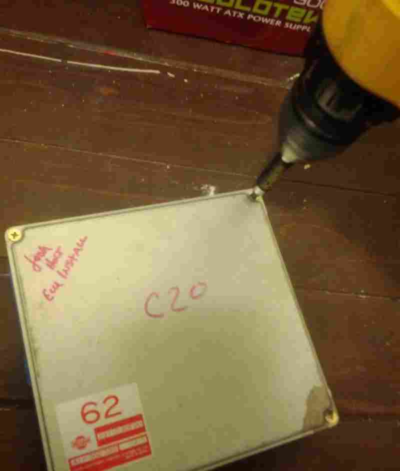
- Remove both the top and bottom case from the ECU. You will want to have the ECU on a flat surface so you can apply a LOT of downward pressure before you start to turn the screw. Nissan ECU screws have some kind of threadlocker on them from the factory and it is VERY easy to strip and/or break them. We highly recommend the use of a screw gun like the one pictured here.
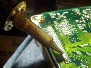
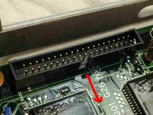
- Find the 20×2 connector where NEMU will attach. Use your De-soldering Iron to cleanly remove the solder from all 20 holes. Be careful to not overheat the circuit board and burn up a trace. ( Click herefor a video of a professional using high quality tools to effectively de-solder components.)
- Remove the 20×2 pin header connector and provided solder from the bag included in your NEMU kit. Push the pin header through the 20×2 holes in the PCB you just de-soldered. Make sure the alignment keyway faces INWARDS.
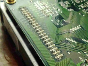
- Use your soldering iron and the included length of solder to solder all pin connections.
Be careful not to use too much heat, too little heat, too much solder or too little solder. Click Here for a video of a professional using high quality tools to effectively solder. Davy Jones’ EEVblog also has a great series of video tutuorials on soldering. (Part1Part2Part3)
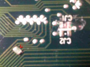
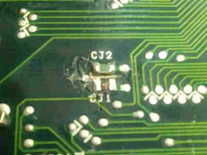
- Look at the bottom of the ECU. Find the surface mount jumper labelled CJ1. Use your hot air pencil and tweezers to remove and grab it.
If you don’t have hot air, you can CAREFULLY use a soldering iron placed parallel to the jumper to melt its solder connections while applying GENTLE pressure to free it from the PCB.
- Use your tweezers and soldering iron to re-solder the jumper in CJ2 position instead of CJ1 where it was originally installed. This enables the 20×2 port instead of stock ECU operation. If you lose or damage the jumper removing it, you can use a small piece of wire or even a solder bridge.
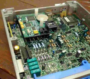
- Take your NEMU circuit board out of its protective anti-static bag and gently install it in the shrouded 20×2 pin header that you have just installed. This is just a temporary install for fitment purposes – you do not need to fully seat the NEMU at this time. Treat it carefully.
- Now find the 4 pin connector with 4- 6″ wires hanging out of it.
- For the sake of tidiness, trim off the black wire as it is not used. (This is not REQUIRED but recommended)
Note: the position NOT the color of the wire is important. If your pigtail has a different color wires, pay attention and pick the wire in the same spot in the connector.
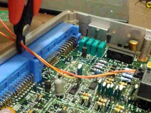
- Each of the three remaining wires needs to be soldered to a pin on the blue ECU connector. The wires provided are much longer than they need to be. We are going to trim the wires so they are closer to the length necessary. Plug the 4 pin connector into the NEMU board and then move the three wires to the center of the blue connector for sizing purposes.
- Make a cut right by the blue ECU connector to get started. You’ll find that having wires that are almost the right size makes them a lot easier to handle.
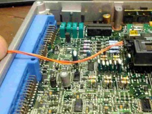
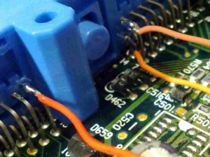
- The red wire is going to get soldered to the ‘top’ pin closest to the center divider on the left side. Cut it closer to size. Remember, it’s a lot easier to cut it shorter again than it is to have to solder two wires together to lengthen it! If in doubt, leave it longer. Repeat the sizing procedure for the yellow and orange wires. They will go to the top and bottom pins closest to the center divider on the right side. See the following picture of how things will look when they’re done: (The colors look a little funny because of lighting – red on left, orange center lower, brown center upper)
- After you have sized all 3 wires, gently squeeze the black locking tab on the connector to remove the 4 pin datalogging connector from the NEMU board. You’ll find the rest of this procedure is a lot easier with the freedom to move around.
- Strip about 1/4″ to 1/2″ of insulation off the end of each wire with a pair of wire strippers.
- Using the soldering iron, warm up the strands of each exposed metal wire for a few seconds. After you’ve warmed them up, gently touch some solder to the wire itself NOT the soldering iron. When it is hot enough, the wire will wick up the solder. (this is called tinning the wire. You can see a pro demonstrate here or here ) You just need a little bit of solder – don’t goop it. Having the wires tinned will make it much easier to attach them to ECU pins.
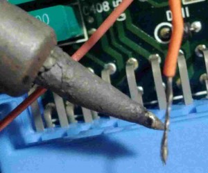
- I prefer to start with the most difficult wire to solder so there aren’t other wires in the way – I personally think this is the lower connection on the right side, with the orange wire. Before trying to solder this connection, we are going to bend the tinned end into a ‘U’ shape so that it will “hook” on the pin.

- Trim the wire so it is quite short. You don’t need much of a hook for this technique to work effectively.

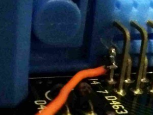
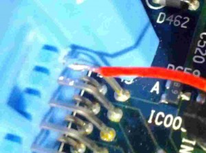
- Hook the orange wire on the lower pin on the right side. You may find it is helpful to squeeze or even wrap the tinned end of the wire around the pin so that it will stay on the pin without you actually holding it. Apply heat to BOTH the ECU pin and wire with your soldering iron for at least 3-5 seconds and then apply solder to the area where the pin and wire are touching, NOT the soldering iron tip itself. This is a little tricky, but hopefully you should get something that looks like this:
- If you like the hook-and-wrap method, you can use it for the remaining two wires. I’m going to demonstrate a different method that works equally well, especially because we can reach the pins easier. Let’s grab the red wire next. Keep the tinned end straight but trim it so it is a similar size to the pin you are going to be soldering it to.
- Bring the trimmed red wire to the pin. Lay it on top of the pin so that they’re on top of each other. Apply heat to BOTH the wire and the pin for at least 3-5 seconds, usually by placing the tip of the iron on one side of the pair where it makes equal contact with both the wire and the pin. Then apply solder where the two are touching, NOT to the soldering iron itself – this is usually done to the opposite side that the iron is touching. This is a little tricky, but hopefully you’ll end up with something that looks like this:
- Repeat the previous two steps for the brown wire, which attaches to the pin above the orange wire to the right of the center divider. After this, you should have all three wires attached like so: (The colors look a little funny because of lighting – red on left, orange center lower, brown center upper)

- Next, we need to modify the case to give the USB cable room to exit. I used the oval area near where you normally look at the LED to check codes. I cut the metal case with a large pair of diagonal cutters.
- Now would be a good time to firmly install your NEMU board in the 20×2 header and connect the 4 pin black datalogging connector with wires soldered to ECU pins.
- Connect the miniUSB->bulkhead cable in your kit to your NEMU board. For extra safety (i.e. leaving your laptop plugged in and walking off) I generally tie a pretzel knot in the cable immediately before it exits the ECU case so that the knot will absorb any yank or pull. Use the supplied zip tie to securely attach the USB cable to the case of the ECU.
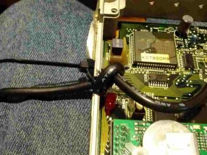 Once you’ve done this, trim the zip tie for tidiness.
 - If you’re going to be using the extra analog inputs offered by NEMU, repeat the last step with the AuxBox cable. This cable has a ethernet/phone jack looking RJ45 connector on one end and a small black plastic box on the other.
- Re-install the case on the ECU.
- Go to www.nismotronic.com for the lastest software download.
- Enjoy your product!
