The ‘G3’ Switching Adapter
(also: Using the ‘EX’ with the G3)
Note: This product was updated in 2015. The original documentation (which still applies) follows with a discussion of differences between the original and current hardware.
For placing several different binaries on a single chip for GM applications, the G3 adapter is the hot ticket. By ‘stacking’ the binaries on a large-sized memory, and using the included switching ability, you can swap between different programs on-the-fly while the car is running. You could have ‘Valet’, ‘Economy’, ‘Nitrous’, or whatever else you want to put together.
First a little background. A memory chip is accessed by changing the state of various connections or pins. Some of the pins are called address lines. They tell the chip which data to present. There are low address lines (A0 through A14) and high address lines (A15 through A18). The larger chips like the AM29F040 have A0-A18, or 19 address lines. What the G3 adapter does is take ‘manual’ control of the address lines A15-A18. If you study binary stuff, you’ll know that this will give you 16 different memory ‘banks’ which can be selected.
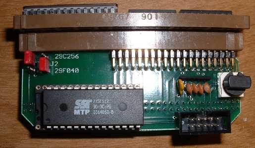
On the G3 are several components, including one thermofuse (looks like a capacitor) to protect against shorts when using the ‘EX’ module, four capacitors which help dampen RFI pickup from the EX cable, two jumpers to set the operating modes (see below), and a rotary DIP switch to select which bank of memory is to be accessed.
Installation instructions for the G3 adapter are very similar to those for the ‘G1’ adapter, so see the section under ‘G1’ instructions for guidance in this regard.
Think of the G3 as an old-style channel selector on a TV. You just turn the knob, and the car’s ECM will see a different channel or ‘bank’ of memory. Put the switch to position zero, and all the ‘high’ address lines will be set to 5v. Thus, the actual memory location that will be accessed on a 29F040 will be 78000-7FFFF. If the switch is set to position ‘F’, then all the high address lines will be set to GND, or ‘low’. In this case, the reference memory will be 00000-07FFF. You can see how this lets you put up to 16 programs on a single chip and select between them. The switch positions are numbered 0-F, which is just hexadecimal for zero through 16.
There are several different hardware configurations which are possible with the G3. This increases flexibility along with the confusion factor. Let’s look at these combinations individually:
1) Putting a 29F040 chip in the G3, and operating with an ECM that originally takes a 27C128 (16k bin) or 27C256 (32k bin). This gives you 16 bins.
2) Putting a single 29C256 or 27SF512 chip in the G3, operating in ‘passthrough’ mode with no switching.
3) Putting a 29F040 chip in the G3, and operating with an ECM that originally takes a 27C512 (64k bin). This gives you 8 bins.
4) Putting a 27SF512 chip in the G3, and operating with an ECM that originally takes a 27C256 or 27C128. This gives you 2 bins.
The most typical cases are (1) and (2), so we’ll talk about them first.
For operating instructions on the ‘EX’ module, see the bottom of this page.
Case 1: Originally a 27C128 or 27C256, use a 29F040 chip to switch between 16 programs.
First thing you will want to do is ‘assemble’ your big 512k binary from a group of smaller ‘stock-size’ binaries that you create or collect. The screenshot shows the configuration screen in ‘TunerPro’ under the BIN stacker function whereby the proper settings have been selected.
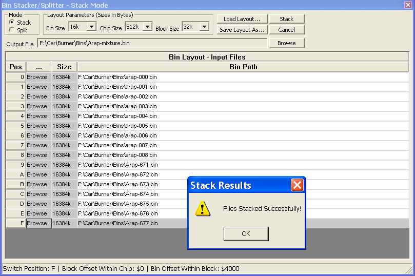
Notice how the bin size here is 16k (originay a 27C128) and the chip size is 512k (for a 29F040). The switch size for the Case-1 hardware configuration is 32k. This is going to create a 512k fie that you can then burn directly to a 29F040 chip without any offsets. Also note that TunerPro does the BIN order reversing for you, so all you need to worry about is which switch position is associated with which BIN.
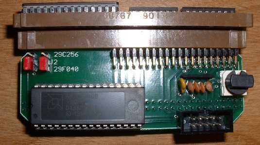
The jumper positions for this Case-1 are such that both jumpers should be placed in the ‘down’ position as shown in the picture. This will allow full access to a 29F040 chip’s memory banks via the switching with bank sizes up to 32k. Make sure the notch on the chip is facing to the left as shown.
Case 2: Originally a 27C128, 27C256, or 27C512 chip, use a 29C256 or 27SF512 chip as a single-program pass-through application.
If you want to use the G3 as just a straight adapter and not a switcher, this can be done very easily. Just program the chip as you normally would for a single-program application and put it in the adapter.
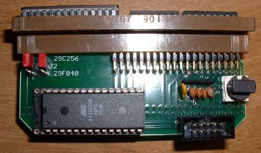
Only trick is to make sure that you set the jumpers to the ‘up’ or 29C256 position. This will allow the G3 to act just like a ‘G1’ adapter, passing the signal directly through and bypassing the switching functionality. Make sure the chip is moved over to the right, with the notch facing left.
Case 3: Originally a 27C512 chip, use a 29F040 chip to switch between 8 programs.
Now we’re getting to some more ‘flexible’ appication of the G3. For this case, the jumpers should be set as shown, with J1 in the ‘down’ or 29F040 position and J2 (right) in the ‘up’ position. You still stack your BINs using the TunerPro Bin Stacker, but the settings should be such that your Bin Size=64k, Chip Size=512k, and Switch Size=64k.
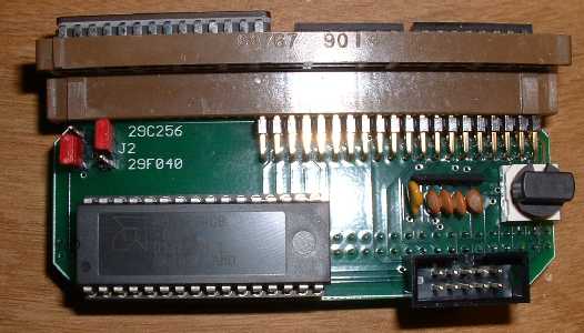
When switching in this mode, there will be a little difference. In this mode, position 0-1 are the same and 2-3 are the same and so on. So, in terms of which BIN you will be accessing, you’ll be seeing BIN0 in positions 0-1, BIN1=2-3, etc through BIN7=E-F. This gives you 8 binaries you can put on the chip and select from, with a switch occurring every ‘other’ switch position.
Case 4: Originally a 27C128 or 27C256 chip, use a 27SF512 chip to switch between 2 programs.
OK, so you don’t want to run 16 different binaries? Just two? Here’s an option for you. Set up your BIN in TunerPro again, with the Bin Size=16 or 32k, chip size=64k, and switch size=32k. Set the jumpers with J1 in the ‘up’ position and the J2 in the ‘down’ position. This will allow the A15 line to get switched every other switch position.
When operating in this mode, the first bin will be accessed at switch positions 0,2,4,6,8,A,C,E and the second BIN will be accessed in the other positions. This gives some switching flexibility without the confusion of millions of binary files.
That’s about it in terms of G3 operation. Again, the installation is pretty much the same as for the G1 so see that section for instructions in that regard.
Using the ‘EX’ module:
The function of the ‘EX’ module is that of a remote BIN switching device and display indicator. When used with the G3, the ‘local’ G3 rotary switch should be placed in the ‘0’ zero position!
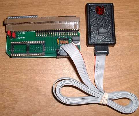
If you want to have a ‘AntiTheft’ or ‘Valet’ mode, you should put that binary in position zero, so you can disconnect the EX and carry it with you. It can be unplugged from the ribbon cable at any time. Don’t worry about plugging it in backwards. It won’t short out, it just won’t work right and won’t light up. If it lights up with the car on, you’ve got it right.
Revisions of the ‘G3’ Switching Adapter
As of 2015, there are two different versions of the G3 Adapter.
The first version has a rotary switch on board and a single 10 pin connector. This is the version that this article has discussed so far. It was manufactured up to 2015:

The second version does NOT have a rotary switch. Instead, it has two connectors – one 10 pin (like before) and a provisoin for a 4 pin (new, open not installed in this picture). It was manufactured starting in 2015:
Fortunately, they function nearly identically. The new version is simplified with fewer configuration steps required due to having fewer jumpers. Both versions can be used on the same platforms for the same thing – allowing multiple programs to be used on OBD1 GM vehicles.
- The early version can be used for switching without any external hardware via the knob. The current version requires either the EX remote (which connects to the 10 pin connector) or a rotary switch with 4 pin cable.
- The current model only switches three address lines allowing a maximum of 8 programs, regardless of the program size. Earlier models supported switching more address lines in some configurations
- The current model will only function in pass-through mode for a single program when using a 28 pin chip. The previous model could support switching between two 32k or 16k programs with a 28 pin 512k chip.
- The current model has only one jumper which selects whether a 28 pin 27SF512 chip or 32 pin 29F040 chip is installed. The earlier model had a second jumper which selected the program size. The only jumper that needs to be adjusted on the new model is to select which chip (27SF512 vs 29F040) is installed – the current version will always function as if J1 was set for 64k operation.
- The current model always presents 64k chunks of memory, i.e. if J1 on the earlier model was set for a 64k block size. The earlier model could present smaller chunks, the current model only presents 64k chunks. When using 16k or 32k bins with the current G3, ensure they are arranged in the top section of a 64k block.
