A lot of the questions we get either via email or on the support line boil down to, “how do I program a chip?”
You asked, we deliver! This tutorial is going to picture the BURN2 but it applies equally to the BURN1 and APU1/AutoPROM as well.
Step by step:
- Get out your burner and a chip.
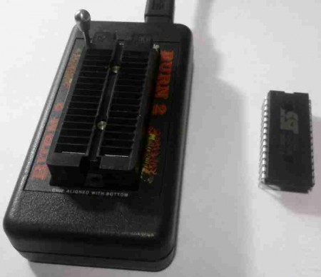
Our burners will work with the AT29C256, SST27SF512, AM29F040 and F3/F3v2 chips we sell.
Our burners will NOT program 27C32, 27C128, 27C256, 27C512 chips but it will read them. - Plug the burner in to your laptop’s USB port.
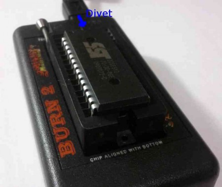
- Install the chip per directions printed on the burner – the unused pins should be closest to the metal handle. The divet on the chip used to mark pin 1 should also face the metal handle.
- Fire up our Flash n Burn software. (If you do not have Flash n Burn, see here to download it)
- Assuming that your drivers are loaded and your hardware is working, you should see this screen after the software loads:
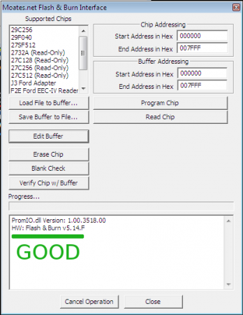
If instead you see something like this:

“No Hardware Found” means that you should see the BURN2 troubleshooting guide, - Next, select the chip type from the list in the upper left hand corner. ( 28 pin = SST27SF512 *OR* Jaybird/BURN2+FA with F3 chip = J3 Ford Adapter)

- Chips need to be be blank before you program them. Click “Erase Chip” and then “Blank Check” This will erase the chip and then perform a check to see if it is blank. If it succeeds, you should see this:

If you see this instead:
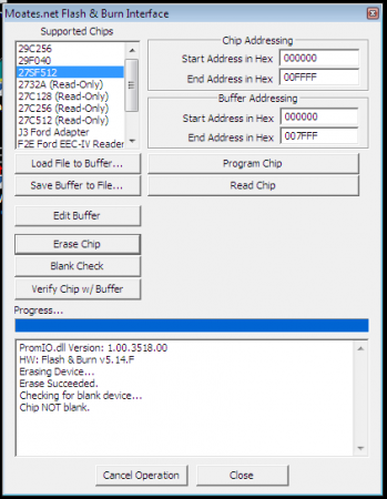
Try another chip. If your burner fails to erase several different chips, you probably have fake chips. If you are sure your chips are not fake, contact us for further assistance. - At this point, you have a blank chip correctly inserted in your burner with the correct chip type selected. The next step is to load the file you want to program to the chip. To do this, click “Load File to buffer” and then point it at the file on your PC that you want to program.
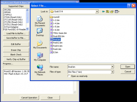
- Double check addressing settings. (This can be tricky – there is a whole article on it to help you.) In most cases, the software will automatically set these for you. These settings are important because most of the chips used in ECUs are a smaller capacity than the chip you are programming. You need to make sure the program you put in the chip ends up in the top (end) of the chip, so these settings matter. A short list of chip addressing settings:
- 64k bin: 000000 start 00FFFF end ( SST27SF512 chip )
- 32k bin: 008000 start 00FFFF end ( SST27SF512 chip )
- 16k bin: 00C000 start 00FFFF end ( SST27SF512 chip )
- 4k bin: 00F000 start 00FFFF end ( SST27SF512 chip )
- 56k Ford EECIV bin: 032000 start 03FFFF end ( Ford F3 chip )
- 256k Ford EECV bin: 000000 start 03FFFF end ( Ford F3 chip )
- 112k Ford EECV bin: SPECIAL need other software ( Ford F3 chip )
- 216k Ford EECV bin: SPECIAL need other software ( Ford F3 chip )
- BEB files CANNOT be programmed with FnB / TP. Must program using Binary Editor
- eBIN file CANNOT be programmed with FnB / TP. Must program using EEC Editor.
- Click “Program Chip” You should see a progress bar march across and then the software report “PROM I/O succeeded.”

- Now click “Verify Chip w/ Buffer” This will read the contents of the chip back and check them against the program you have loaded in the buffer. If this test passes, you can be confident that the chip was programmed correctly.

You should see: “SUCCESS:Verification Succeeded” as the message reported back. If you see this, you are DONE and the chip is programmed correctly! If instead you see “FAILURE: Verification Failed (not matched)” you will need to do some troubleshooting:
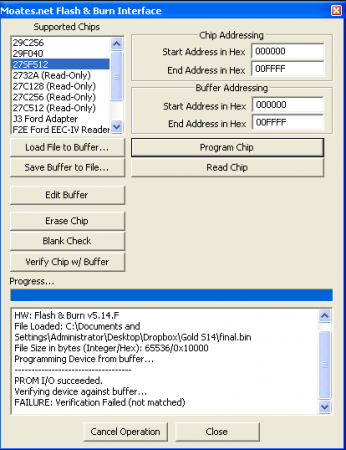
- Check and make sure the chip is inserted firmly in the socket. Remove it and re-insert it to be safe.
- Re-erase and blank check it. If it passes a blank check, try programming it again.
- If it fails the blank check, try another chip. Failing blank checks is a common sign of fake chips.
- Try another chip purchased from us, xenocron.com, poweraddersolutions.com or another known legitimate source.
- If you’re still having trouble, contact us.
